


|
|
|
|

Important notice: The CSA web site was re-designed in August of 2010. Some documents then available were considered complete and static; so they were not included in the re-design and were not updated. This is one of those documents. Information about dates of posting and revision remains here, but there will be no revision of any kind after August, 2010.
| Contents | |
|---|---|
Computer-assisted design (CAD) software has the potential to revolutionize data recording and presentation for archaeologists and architectural historians. Instead of making static, scaled, 2D drawings, scholars can record the geometry of their subjects and display the results as 3D models -- on screen or on paper. The models may be viewed from any vantage point and at any size, as perspective or axonometric drawings, and traditional plans and elevations at any scale may also be produced. Furthermore, the models can be constructed to provide views and drawings of the subject at various stages in its history, with or without reconstructed portions, and as imagined by various scholars. Individual views can be further modified by other software to provide photo-realistic images or annotated drawings similar to drawings produced by hand. In addition, full, unscaled dimensional information can be retrieved from the model on command, providing access to the geometry of the subject at originally measured levels of precision.
Even when 3D models are not necessary, CAD offers important benefits. Dimensional information is better preserved, and multiple views and interpretations of the subject are instantly available without laborious manual drafting. Plans -- with or without specific portions of the subject to emphasize points of interest, to show development, or to add reconstructions -- can be produced on demand, at any scale, on paper or on screen.
A CAD model -- whether 3D or not -- is also a resource that can be used as fully and effectively by successive scholars as by those who construct it in the first instance. Properly archived, the CAD model is a permanent resource, presenting geometry and interpretations to users in the future as to those in the present. Furthermore, the preserved CAD model is a base to which future scholars may add competing interpretations or restorations, making the original scholarship as well as new ideas based thereon fully accessible to others.
My own experience making and using CAD models, particularly the model of the older entrance to the Athenian Acropolis, both informs and reinforces the foregoing. I have used models to find or confirm measurements, to analyze the remains, to make drawings for display on paper and on screen, to view the remains from various points of view, and to provide full access to the model for others. CAD models have also been used to generate renderings that aided my understanding. CAD software has consistently provided the benefits I expected and often provided others that came as surprises.
Despite its potential, CAD software has been adopted slowly, its use apparently limited by misunderstandings and mistaken perceptions of its complexity. (CAD programs are not easy to learn, but the typical scholar uses only a small fraction of the available features, making the programs far less difficult to learn than many potential users believe.) Therefore, this document has been designed to provide encouragement and guidance for individuals and organizations involved in the creation, maintenance, use, and long-term preservation of CAD-based digital resources in archaeology and architectural history. Given the number of different users of and uses for CAD technology, parts of this guide will be of limited use to some practitioners and crucial to others; readers should be aware that they may find some parts of the guide to be relevant to their work while other parts are not.
As well as containing useful generic information about CAD and its use in archaeology and architectural history, the guide includes discussions of the processes of long-term preservation, archiving, and effective data re-use. As a result, the importance of adhering to recognized standards and the recording of essential pieces of information about a given resource are dominant recurring themes, and the issue of standard digital data formats will recur regularly. Using recognized standards and avoiding proprietary digital data formats will smooth the transition of digital resources into an archival environment and ensure that they can be re-located and re-used in the future.
This guide contains a basic description of computer-assisted drafting or computer-assisted design (CAD) software, discussions of its use in a variety of situations, descriptions of data acquisition and capture methods, good practices in the use of the software, and information about archival practices with CAD files. In addition, there is a glossary of terms used in the guide and in CAD generally. (Words that are underlined in the text have been linked to appropriate entries in the glossary. When a link is activated, the glossary will open in a separate window, with the term in question at the top of the page. Underlining is the only indication that a term is linked to the glossary; the normal color change to indicate a link has been disabled to minimize distractions. If your browser has been set not to underline links -- a possibility in the preferences settings -- you will be able to locate the linked terms only by the change in cursor shape as the cursor passes over the linked term.)
It is important to note what the current guide does not cover. It is not intended to be an exhaustive introduction to the underlying origin, theory, and technical implementation of CAD. Nor is it a prescriptive manual on how best to use CAD software. The aim of the author is to introduce practitioners to issues of importance for use of CAD in archaeology and architectural history and, to the extent possible, to suggest standards and frameworks that are appropriate for scholars. No particular software products will be recommended here. The present document constitutes a guide as opposed to a manual.
Regardless of whether one is using CAD software to create an extremely complex, 3D object in the computer or a simple paper drawing, the reasons for using CAD for any specific project should be clearly examined. A great deal of work will be required, even for relatively simple projects; so the use of CAD should not be appended to a project plan simply to provide an appearance of modernity. One of the aims of this work, in fact, is to make clear both the benefits of using CAD and some of the difficulties so that its use may be evaluated in context.
CAD software is, most simply defined, software intended to facilitate the making of architectural and engineering drawings. Note the emphasis on drawings. Early CAD programs were strongly focused on the production of paper drawings, because the design process had been equally focused on paper drawings. The design process required architects and engineers to condense their complicated 3D ideas into simpler 2D paper drawings. Although CAD programs did not necessarily make the production of an individual drawing quicker or easier, they did make it far easier to complete the whole process of making, editing, and printing drawings on paper at scales necessary for specific purposes. Those paper drawings then provided the information required to create actual physical objects. They were, as drawings must be, 2D abstractions of 3D realities -- or planned realities. Of course, the objects drawn were not necessarily complex, but they could be -- and the more complex the object the more useful the CAD program. In time, stronger computers permitted CAD programs to became more powerful and robust, and the emphasis switched from the drawings to the objects. That is, the CAD programs made it possible to concentrate more and more on the objects being designed and less and less on the paper drawings produced. With stronger computers and better programs it was possible to design -- and quickly visualize - - in three dimensions, not in a series of 2D abstractions intended to represent 3D reality. Using CAD became part of the design process, not simply the drafting process.
Most of the CAD programs available today are capable of fully 3D operations, but CAD programs can still be -- and often are -- used to create simple, 2D drawings such as a plan of a single-level archaeological site. CAD programs can be very useful in such work; it remains effective, after all, to reduce complexity with plan views.
Since CAD programs now work in fully 3D mode, the 3D programs create digital versions of complex 3D objects, not just drawings. Drawings can be produced, of course, but there is no single drawing or group of drawings that, taken together, definitively represents the object as a full-scale model would -- and as a CAD model does. Each drawing is just one view of an object, the full reality of which exists in the computer model. Therefore, the term model is often applied to the product of a CAD project, and that term will be used here. The term may seem to imply a 3D model, but it should be taken more broadly, to indicate a complex but not necessarily 3D version of the object under study.
Model will also be used as a verb to name the process of making a digital model. Again, the implication of three-dimensionality is not intended; the intent is to indicate complexity and to avoid the use of draw and its derivatives, all of which imply one or more physical drawings and the process of making such drawings rather than the more complex computer file that is the product of a CAD project and the more complex process of making a CAD file.
The use of the term model may also seem to imply a single entity, one model of an object that is, in some sense, definitive. That implication is not intended by the use of the term here. Indeed, a single model may contain several phases of a particular object, multiple incarnations, or even competing reconstructions, each of which provides a complete model of an object. A CAD model may therefore represent multiple iterations of its subject.
As previously stated, paper drawings of complex objects are necessarily 2D representations of real-world objects; so architects and engineers have depended on a series of drawing conventions to permit the third dimension to be indicated. Engineers, for instance, generally show the front, right side, and top of an object, adding the bottom, left side, or back only if necessary. Broken lines are used to indicate lines that are hidden in the particular view; another line type is used to indicate the center of a circle; another to indicate the longitudinal axis of a cylinder; and so on.
Figure 1 is an example of an engineering drawing of a child's simple wooden block with inset letters on each of the six faces. Front, right side, and top are shown. A left-side, back, and bottom view might also be necessary, but they are not included here. An engineer would have no difficulty at all working with such a drawing, though dimensions that are not included here would be required.
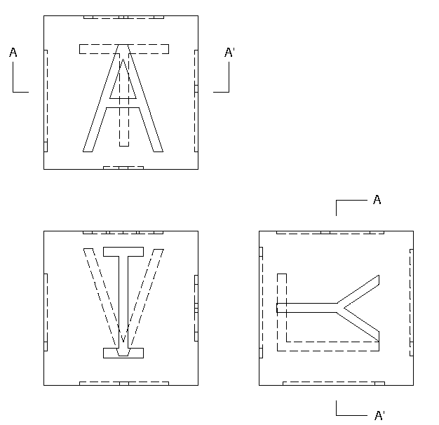
Figure 1. Engineering-style drawing of child's block. (Dimensions not shown.)
Architects generally draw plans and elevations, with many separate drawings of details (and often cross-sections to indicate particular structural details).
Figure 2 shows a simple house plan with walls, foundations, and so on. Again, dimensions have been omitted, but an architect -- or, more to the point, a contractor -- would understand this drawing easily.
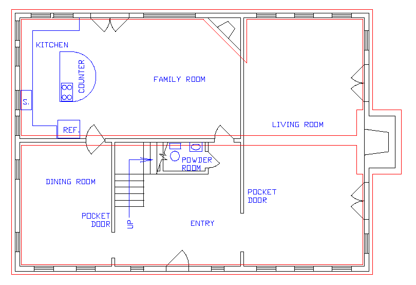
Figure 2. House plan, ground floor: with foundations (in red), labels, interior kitchen layout, plumbing fixtures in the ground-floor toilet (labeled "powder room"), windows, and doors (with indicators of the swing directions of the doors).
Both architects and engineers have developed conventions for illustrating their creations in three dimensions. Engineers regularly use axonometric views; such views resemble perspective views but lack foreshortening. Architects often make sketches of building exteriors, sometimes with proper mathematical accuracy but more often as impressionistic versions of their structures. In either case, the 3D views may be quite necessary to provide understanding for a customer or client, particularly one who finds it difficult to visualize something presented only as a plan.
Figure 3 shows an isometric view of the child's block in Figure 1.
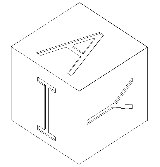
Figure 3. Isometric drawing of child's block.
Archaeologists and architectural historians who use drawings to record real-world objects under study also use conventions to indicate meaning. In such scholarly settings, however, the 2D drawing may be intended less to convey a 3D impression than simply to record a basic 2D view with details such as wear marks or different materials indicated to add information. Such drawings are intended to record the objects under study but not necessarily to convey their true 3D reality and certainly not to make it possible to construct the object(s) depicted. (A good drawing of the sort just described would not reproduce well on the Web; the details in such a drawing require high resolution and/or large size to be reproduced well. Readers are encouraged to look carefully at published examples from their own disciplines. An excavation report or a monograph concerning a single building should provide good examples.)
CAD programs are capable of creating 3D models, complete with all the complexity of the real world. Indeed, most programs in the market must offer 3D modeling capabilities if they are to sell, though many inexpensive programs offer few 3D modeling features and some moderately-priced programs are so closely tied to paper-drawing practices as to be difficult to use effectively for 3D modeling.
The difference between a 2D drawing and a 3D model is enormous. Consider figure 4 with various versions of the child's simple wooden block with inset letters. Each is an axonometric view providing a good sense of the block without perspective. (Perspective drawings could have been made as well, but the process of making them is slower and somewhat more cumbersome.) Taken together, these drawings make the design of the block very clear. Since the views shown come from a CAD model, more could have been made from any angle, from near or far. Any number of different views could be generated to make sure the intent of the design is clear.
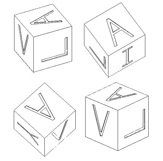
Figure 4. Various views of child's block.
An engineering drawing could also be made from the model for manufacturing purposes. Of course, modern manufacturers would probably produce the block directly from the digital model, without intervening drawings on paper.
A similar style drawing -- an axonometric view -- of the extant remains of the older propylon in Athens (the older entrance to the Acropolis, prior to the Propylaea, built and rebuilt twice between 490 and 437 B.C.) is also easy to understand, though the subject is much more complex, because the 3D view is so natural.1
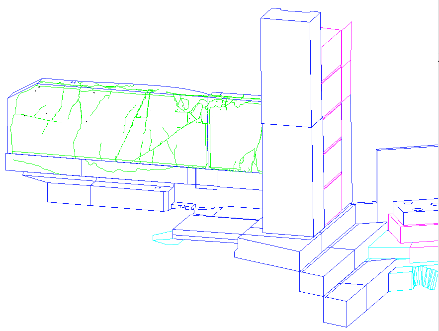
Figure 5. Axonometric drawing of a portion of the older propylon on the Athenian Acropolis. (Blue lines for marble, magenta for the soft local limestone called poros, cyan for bedrock, green for the cracks on the marble blocks, and black for holes drilled into the marble in antiquity.)
An important distinction in CAD models and modeling practices should be introduced at this point. Figures 3 and 5 have real-world appearances, despite the fact that they are only line drawings. The lines in the drawings are those an artist might draw when sketching. Of course there are many parts of the objects that are not seen from a particular vantage point. The lines that might represent those parts of the objects are hidden in the drawings -- as in the real world -- by intervening objects.
Figures 6 and 7 show what would happen if those hidden lines were visible in the drawings. These drawings are very difficult to "read" because of their complexity, but they would be the best possible results from a so-called wire-frame model, a model consisting only of lines and including no surfaces. Such a wire-frame model can be fully three- dimensional; all the lines in Figures 6 and 7 are properly oriented in 3D space. However, there are only lines represented, no surfaces, in such a model. Therefore, all the lines that define the objects are visible in these drawings, whether they would be visible in the real world or not. If there are no surfaces, those lines must be drawn; there is no way for the CAD program to know which lines should be hidden from a given vantage point. Figures 4 and 5, on the other hand, show what can be done with models that include explicit definitions of surfaces. When asked to produce a drawing from a specific vantage point, the CAD program can calculate the results and make certain that the effects of intervening surfaces are taken into account. (Such a drawing is usually called a hidden-line drawing, and that term will be used throughout this work.)
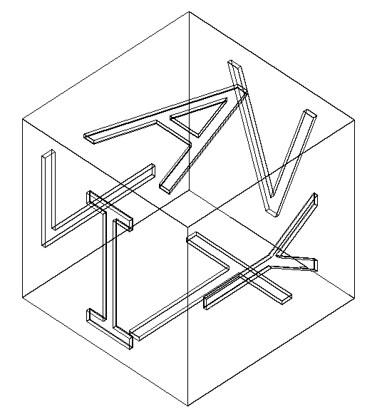
Figure 6. Isometric drawing of child's block. (Wire-frame version.)
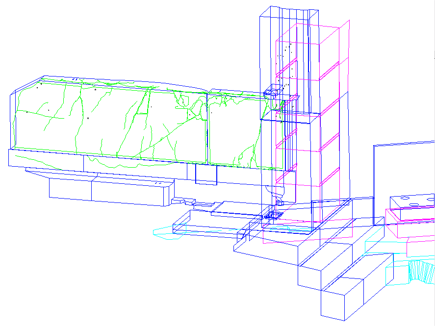
Figure 7. Axonometric drawing of a portion of the older propylon on the Athenian Acropolis. (Wire-frame version. Colors as in Figure 5.)
In addition to wire-frame and surface models, there are also solid models. In such models the data indicate not only surfaces but the full, explicit boundaries defining solid objects. Since a solid object is explicitly defined as such, a CAD program can automatically produce a cross-section of a solid (Figure 8), something impossible to create from a surface model without considerable manipulation. Furthermore, solid models of objects can have assigned materials, in which case mass can be calculated, as can the center of gravity. More important, stress points and load-bearing capacity can be determined. Views of a solid model -- except for cross-sections -- are identical to views of a surface model,
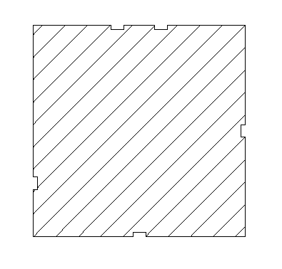
Figure 8. Section of block at A-A' (See Figure 1 for location of plane A-A'.) Note that indentations for letters A (top), Y (right), L (left), and T (bottom) are shown.
One might think that solid models would be preferred for all work, but, in fact, they are not often used in archaeology or architectural history. In such work it is rare that a full solid model can be made without dismantling standing structures, since modeling a solid requires the necessary dimensional information for all of its surfaces. Furthermore, the gain from a solid model would be minimal. Solid models are more complex to make and more demanding of computer hardware; so they are most likely to be used when specific structural questions are at issue, as can be the case with either reconstructions of missing structural elements of a building from the past or plans for complex structural parts yet to be built.
In some cases, even 3D wire-frame models are not possible, and 2D drawings must be sufficient -- because there is not sufficient information, because the reality being modeled or planned is not very complex, or because the matters at issue relate only to the plan. Of course, time and budget constraints may also restrict the complexity of the finished model.
The foregoing discussion implies an either/or creation of wire-frame, surface, and solid models. In reality, however, parts of a complex CAD model may be surfaces, other parts solids, and still others only wire-frame models. Although some programs would not permit such mixing of modeling styles, practical considerations recommend it. For instance, portions of a dismantled structure can be modeled as solids, while standing portions are inaccessible and must be modeled as surfaces only. Similarly, cracked blocks still immured in a wall could be modeled as individual surfaces bounded by the crack lines, but it is much easier -- and more useful -- to model a single surface and then put simple lines on the surface to represent the cracks. Thus, the mixing of solids, surfaces, and wire-frame elements is common and desirable.
The current CAD programs -- whether 2D systems, surface modeling programs, or solid modeling packages -- have an interesting parentage that helps to explain why they work as they do. Computer-assisted drafting programs were developed for architectural use and fitted with certain capabilities so that traditional architectural practices could be continued. At roughly the same time, computer-assisted design programs were developed for engineering, some to make it possible to move directly from product design specifications to manufacturing (particularly the cutting of molds to be used in making plastic objects) and others to permit visualization of consumer products in advance of production. Each of these uses has bequeathed to contemporary users specific qualities of value to scholars in the humanities.
I. 5.3.1 Pin-bar drafting was developed by architects to permit convenient drafting of multi-storied or very complex buildings. Multi- storied buildings have identical exteriors for many floors but may have different interiors. Similarly, complex buildings, whether multi-storied or not, require separate electrical plans, plumbing plans, plans for heating and air-conditioning ducts, and so on. To eliminate duplication of effort, architects formerly drew the structural outline of the building (and common features like elevator shafts) on one sheet of paper, positioned a transparent sheet atop the base sheet (on registration pins, hence the term, pin-bar drafting), and then drew the interior of a specific story on a transparent overlay. In the same fashion, electrical diagrams, plumbing diagrams, and so on could each be put on a transparent sheet, and a large number of such individual overlays could be put on the registration pins together so that the many drawings could be viewed at once -- making all features or only a few visible at one moment, as required.
Computer-assisted drafting programs for architects adopted a mechanism to mimic the transparent overlays used in pin-bar drafting. Architectural CAD programs were designed to permit parts of drawings to be assigned to specific segments, and the segments could be displayed or suppressed on demand. That is, instead of drawing on different transparent sheets, architects drew on different segments of the drawing. Each segment remained a part of a single file, as an individual drawing sheet would be a part of a complete set of drawings.
As with the drawing sheets from which they descended, drawing segments can be spatially or conceptually different from one another. That is, one segment or transparent overlay may include parts of a building for one story while another segment or overlay includes parts for the next story, in which case the two segments or overlays show spatially distinct items. It is equally possible, though, to put the plumbing pipes for the second story on one segment or overlay while putting the electrical wiring diagram for the same story on another segment or overlay, making the distinction in that instance conceptual rather than spatial. The plumbing pipes and electrical wires cannot exist in precisely the same places, but the architect is not trying to define the boundaries within which either can exist. Their physical separation is not the point; their conceptual isolation from one another is the issue.
It is important to realize that models can have segments that are used for conceptually distinct parts of the model, especially since the term used for a discrete drawing segment in a CAD model, layer, seems to imply a physical or spatial distinction. It seems that the term descends from the earlier use of the transparent overlay, but one must not permit the term to cloud the issue. A layer in a computer model may contain items isolated from others for any reasons whatsoever -- spatial, conceptual, or temporal.
Figure 9 (identical to Figure 2, above) shows a simple house plan with walls, foundations, and so on.
Figure 9. House plan, ground floor, with foundations (in red), interior fittings, labels.
Figure 10 shows the same house plan with only the exterior and interior walls, doors, and windows. The difference is simple; the model layers containing the kitchen layout, labels, plumbing fixtures, and foundations were suppressed for this view.
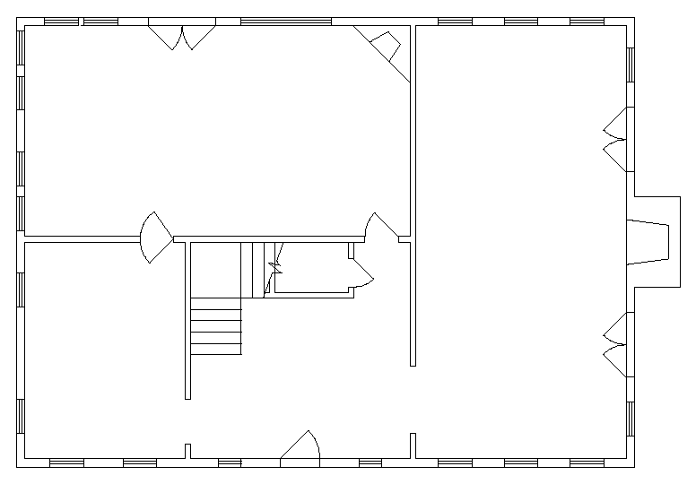
Figure 10. House plan, ground floor, with walls, windows, and doors (and indicators of door swings) only.
Using layers to segment a model is a crucial part of the successful application of CAD to problems in archaeology and architectural history. Different layers in an archaeological model, for instance, might hold materials from different phases or time periods as well as reconstructions designed by different scholars. In an architectural history setting, the CAD version of a building might be modeled as planned, as built, and as modified in the same model, with each version having many common parts but some different ones. An historic building might also include a measured plan on one layer without 3D additions and a digitized version of a published plan on yet another. The segmentation of the model with layers makes new kinds analysis of the model possible; of course, the way the model is segmented has an enormous impact on the kinds of analysis available. A thoughtful design of the layering system is one of the most important parts of creating a CAD model. (It should be said that some CAD programs do not use the term layer, but nearly all use either layers or some analogous system for segmenting the model.)
Figure 11 shows how some of the material from the older propylon was distributed on multiple layers for various reasons. The single paving stone was the only paving stone remaining in situ; it is separate from the other objects because it is a paving stone, not a wall block. The stones of the two lower courses of the wall were trimmed between the second and third phases of the building; so they are separate from the stones above, which were not trimmed. The stone of the string course is not in situ now; so it is on another layer. The cracks were certainly not part of the original construction; so they are separate. Finally, the holes drilled in the marble in antiquity (for hanging trophies?) may have been drilled immediately or not; so they are on their own layer. Everything in the drawing is marble; were any of the blocks not marble, that would have required putting them on another layer. (That is, the system of layering used here separated marble blocks from hard limestone, poros, and bedrock.)

Figure 11. Drawing of a portion of the older propylon showing how many layers make up this small part of the structure.
Other methods for distinguishing objects in a CAD model exist. For instance, some programs permit any object to be given a label, and it would seem that such a process would be more flexible than using only the data segments or layers to make distinctions between and among parts of a model. Unfortunately, however, the other ways of describing objects are not common or uniform among CAD programs, while layers or an analog are common to virtually all CAD programs. As a result, using layers to segment a model not only satisfies scholarly requirements but also works with virtually CAD programs. Other systems might work just as well on a particular model, but the data could not be transferred to another CAD system while retaining the desired distinctions.2
I. 5.3.2 With large projects, for example a large archaeological site or building complex, a single CAD file may become cumbersome and difficult to manage. One problem is simply the size of the file; the bigger the file, the slower all computer operations. Another problem may lie in the complexity of the file and its layering system if the contents are extensive. In such cases, it may be desirable to create separate CAD files for individual elements that make up a large project. For an excavation, for instance, separate work areas might be treated in separate CAD files. Similarly, the CAD model of a civic area might be broken into individual files, each of a single structure. Links or cross-references can then be established to relate the files to one another (and the common Cartesian grid system underlying all the files) and create a composite model, preferably with a single, empty file as the base for all. Any number of CAD files that are linked in this way can be displayed together as if they are part of a single model. Although only one CAD file can be edited at any one time, any changes will be reflected in the composite model. (A layer-naming scheme can still be used, even though there are several files involved, but the same layer-naming system should be used in all the linked files.)
The advantage with such a system of cross-referenced files lies in the ability of the model-makers to work on small files as they create the elements that make up a large model. In addition, different people may be working on different parts of the model at the same time. There are also disadvantages, since editing of many common aspects of a group of files may be more time-consuming than making the same edits within a large file.
If such a combination of linked files is used, the user stands to benefit most if the individual files are commonly used alone. Otherwise, there is little real gain, since using the files together as a composite model is not more efficient than using a single large file. Therefore, it may be desirable to make a large model using cross-referenced files but then to combine them into a single file for use. However, at some point in the complexity of a very large project -- a point that cannot be predicted in the abstract -- multiple files will be necessary because of the complexity of the whole project.
There is one significant problem with using linked files and putting parts of models in different files. The links established from a base file to linked ones may assume specified directory pathways that are specific to the host computer's file structure and that, as a consequence, no longer point to the linked files when those files are sent from one user to another. Fortunately, relative directory paths rather than explicit ones can generally be used, and the model- maker should consult the specific software instructions to be sure to supply such relative pathways. Then the linked files can be found without difficulty.
The key issue in considering the use of cross-referenced files is the utility of the individual files in isolation. When individual files may often be used alone, using linked files may be desirable. No rule of thumb will suffice, given changing computer hardware and software; so creators of models will need to decide individually whether or not individual files are useful in isolation. If speed is not a problem, using cross-referenced files offers a benefit to the end user only when the file becomes impossibly large. Until then, using cross-referenced files may add more problems than benefits. [Note: Very large files may be unusable on computers without sufficient memory (RAM). When the model cannot be stored in RAM, the computer will try to use the hard disk to hold information that cannot be retained in RAM, but the time required to swap information from a single model back and forth between live memory and the hard disk usually makes the model effectively unusable. Therefore, large CAD models require computers with plenty of RAM. Using linked files rather than a single large one has little affect on this problem.]
I. 5.4.1 Among the most important requirements of some early engineering systems was the need to hold precise, explicit dimensions, because they would be passed to machine tools that would ultimately cut parts on the basis of those dimensions. As a result, the computerized drawings could not be dependent on drawing scale or written dimensions; nor could they be two-dimensional. Instead, the locations of all points had to be maintained in the computer file as real-world, precise, 3D coordinates so that the computer could determine, from those coordinates, exactly where and how to cut a part. The computer display, of course, had to be scaled so the user could see the drawing, but the numbers that underlay the display had to be unscaled, real-world numbers.
As a result of this need for precise and accurate representations of numeric data, CAD programs for engineers separated the display of drawings from the underlying numeric data. The underlying data had to be unscaled and as precise as required by the designer. Thus, all points required to define the geometry are recorded with precision to the millimeter, and sometimes far finer tolerances, and embedded in the digital file. That separation of display scale from underlying data has become standard in modern CAD programs, and it provides one of the most important features of CAD software.
I. 5.4.2 Other engineering programs were developed to illustrate the appearance of objects as they were being designed. With those programs engineers could study the results of design choices that affected appearance, e.g., color, texture, and subtle changes in shape. Such programs were particularly important for consumer products that might succeed or fail in the marketplace depending on their final appearances, and those programs required very sophisticated processes for illustrating objects as if they were real. In addition to alterations in the objects themselves, the programs permitted designers to specify lighting conditions in order to see the objects as they would appear under different circumstances.
Figure 12 shows the block we used earlier, but this time it has been treated as a wooden article, with white paint to highlight the letter shapes. It has been lighted and rendered so that we can see it as it might appear to a consumer. Figure 13 shows the older propylon as rendered with a program that permits adding complex textures to CAD models, but this is a rendering of only moderate quality by contemporary standards. The desire for better renderings has spawned an entire program category -- rendering programs that use CAD models to make realistic images.
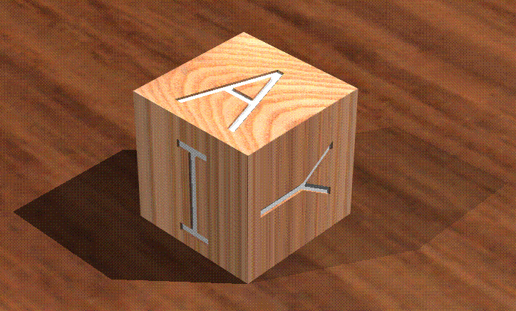
Figure 12. Rendering of child's block on wooden surface (using ray tracing & cast shadows).
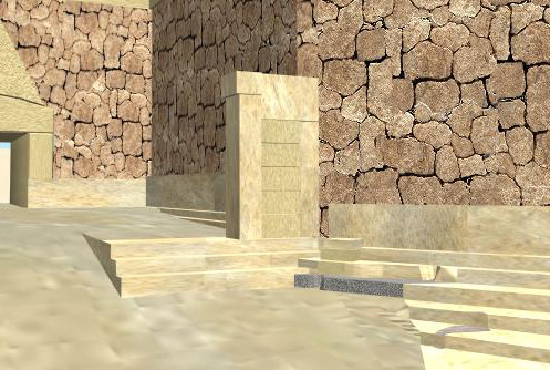
Figure 13. Rendering of older propylon.
Drawing layers, true three-dimensionality, full dimensional precision, and sophisticated rendering -- each was included in some CAD programs from the beginning of the use of CAD, but different features were made available for specific users and uses. Today, however, all are found in most modern CAD programs. Good rendering systems were the last to be added to the CAD toolkit, since they required computing power that has only become available in the last few years. Indeed, the best and most sophisticated renderings still require additional software.
The geometry of a block, artifact, or wall is not all that is important about it; in addition, its material, date of erection, prior use in another place or even another structure, surface texture or paint, etc. may be known and of interest. Connecting such non-geometric information to a model is possible, because many CAD programs have built-in processes to connect individual entities (a catch-all term for CAD lines, circles, arcs, etc.) within a CAD model to additional information held in external data files. Added non-geometric information might include annotations of nearly any kind or detailed information about items in the model. For instance, stones in a model (either solid models thereof or the surfaces that compose them) of a building might be connected to a data table that specifies for each stone the material, date of construction, surface textures, tooling marks, and Munsel color(s).
One may also use icons in the model instead of entities to lead to an external file with lengthy explanatory notes. Thus, for instance, notes about the prior use of a specific group of blocks or, in general, the blocks used in a certain wall could be attached to an icon -- perhaps an arrow pointing to the blocks in question. Such an icon, located on a layer only for icons leading to notes, would then connect users to the note on request.
Connecting CAD models to external databases adds the opportunity to expand on the information in the model (or contained in the layer-naming system). However, CAD vendors' technology for connecting data to CAD models is proprietary at present. As a result, the data connections will rarely survive translation from a CAD file made with one program into the form used by another. It is therefore preferable to use a system of data linkage that is independent of the particular CAD software chosen (and independent of the database program as well). Data may still be linked to the CAD file, but the link depends upon the CAD user's understanding (via documentation) of the ways the files are linked rather than the CAD program's built-in linkage system. A full description of such a system may be found in Harrison Eiteljorg, II, "Linking Text and Data to CAD Models," CSA Newsletter XIV, 3, (http://csanet.org/newsletter/winter02/nlw0201.html). Illustrations of this system are included there. This system is marginally less convenient than those built into some CAD programs, but it will permit the CAD model and the connected database(s) to be moved from one digital file format to another without fear of data loss.
Considerable use may be made of such capabilities in excavation recording and intra-site studies, for example by linking context and artifact files to site plans. Notes appended to a CAD model through such a system would be useful in virtually any circumstance. Photographs might also be located via database links from a CAD model.
CAD programs can make reasonably good renderings of the models. Figure 12, for example, was made with a CAD program. However, the desire for more and more realistic renderings -- complete with accurate textures, shadows cast on surfaces, reflectivity calculations, even specular highlights -- has generated another software category, programs designed to create photorealistic renderings of models. The best of these renderings are truly photographic in quality, and the programs are not necessarily expensive.
Rendering programs require surfaces; so they cannot be used with wire-frame models. For best results, one also needs photographs of materials found in the model so that samples of the real textures can be used.
Rendering programs use CAD models as their starting points, but the geometry so painstakingly built into CAD models is not likely to survive in a rendering program; that is, the rendering program will not maintain in its digital file the level of geometric precision used in the CAD model. Nor will a rendering program permit retrieving geometric information from the model. Therefore, the CAD model should be retained as the scholar's documentary source.
Rendering programs produce individual images; virtual reality (VR) programs go a step further. They create interactive environments with relatively high levels of photorealism. That is, rather realistic models are presented via a system that permits the user/viewer to move around within the model and to watch his/her view of the model change in response to that movement. These programs, at a minimum, offer real-time interaction between the user/viewer and the model. The view on a computer monitor is constantly changing to reflect the current position and vantage point of the viewer.
Some VR systems involve immersive technologies -- usually head-mounted viewing goggles and wiring to permit the computer to track the motions of the viewer. The viewer is then free to move about in a room, with only the model visible in the goggles. As the viewer moves, the computer tracks the movement and presents constantly updated views of the model. Some of these immersive technologies are so sophisticated that the user may wear gloves that are also wired to the computer so that hand movements -- even picking up a virtual object in the model -- can be included in the virtual world.
Whether immersive or not, VR technology is interactive. As a result, the views on screen are not nearly as realistic as those produced by good rendering programs. The speed with which the on-screen view must be recalculated and displayed is such that the careful calculations of shadows and reflections of the better rendering programs cannot be made fast enough. Users, however, are often drawn into the scenes by the interactivity and, in some sense, ignore the lack of realism. Instead, they focus on moving in space, looking for particular items or details, and understanding the totality of the virtual environment.VR programs require that the model be simplified or very limited as to size. As a result, the CAD model, once again, must remain the crucial documentary source. Any VR model -- at least for now -- must be seen as a visual presentation, not a scholarly data source. That is not to say that VR cannot be used to present scholarship, but the model will not contain the geometric information from its CAD ancestor; nor will it be possible to retrieve any geometric information from the VR model.
To summarize, there are many important reasons to use CAD to record archaeological and architectural remains. First, CAD models can be fully three-dimensional whereas a set of paper drawings can, at best, only provide a few 3D views. Second, dimensions recorded in a CAD model are not scaled; therefore, any dimension can be retrieved from the model at any time and with the precision used to take the original measurement (unlike the retrieval possibilities from scaled drawings, which are limited by the scale chosen and by the two-dimensionality of any drawing). Third, the use of layers makes it possible to record material with great complexity and in a way that provides both considerable analytic potential and a virtually infinite number of potential views of the model. Fourth, data may be attached to items in the CAD models, making the combination of CAD model and tabular data more powerful than either alone. Fifth, CAD files may be used by other program types, specifically rendering and virtual reality programs, to provide superb visualization possibilities. Sixth, the CAD model is a scholarly resource for the future of unmatched value. Any scholar who wants to deal with the subject modeled has its full geometry available as well as the geometry of any suggested restorations and may, with that base, add new suggestions or make new interpretations without needing to re-create the original model. Finally, there is the previously unmentioned advantage of using an unbroken chain of digital data. Since many data-gathering techniques (yet to be discussed) produce digital forms of data, using CAD files to store those data maintains the digital chain. Once the data are reduced to paper drawings, both precision (due to scaling of the drawings) and three-dimensionality (due to the 2D nature of drawings) must be sacrificed.
One feature that scholars might take for granted in CAD programs, the capacity to make good presentation drawings with ease, was not important to early CAD users; so it may not be included in some CAD systems. Even those programs, however, generally provide some mechanism for exporting a CAD drawing to another program for modification and the production of excellent presentation drawings.
There are some considerations regarding the use of CAD in scholarship that may be considered theoretical or epistemological. They are treated in an addendum to this chapter.
Geographic Information Systems (GIS) programs have some similarities with CAD programs, and there is some confusion between the two. GIS software was developed for geographers, cartographers, geologists, and similar users, with city planners, urban developers, and others using the programs extensively after their introduction. These programs were constructed to aid those working with maps and related tabular data, and, of course, maps are little different from architectural plans. In fact, early GIS programs offered rather primitive procedures for drawing maps. Therefore, CAD programs were often used to create the maps used in GIS programs, and land surveys may be done with either CAD or GIS software. These factors have encouraged substantial confusion about the differences between CAD and GIS programs. Despite that confusion, they are very different in terms of their aims and features, and they have internal data structures that are also very different.
CAD systems were developed for representing geometric objects. The ability to attach tabular data to items in CAD models has been added, as stated previously, but the addition of tabular data is meant to augment the geometric representation of objects. It is not a core feature. A specific artifact in an excavation (or perhaps an icon representing its place and orientation) may be shown in a CAD model, for example, and the geometric representation may be linked to information about the specific artifact in a data table. However, the intent is simply to supply additional information about the artifact to that contained in or implied by the geometric shape and layer designation of the CAD object.
GIS software, on the other hand, has always emphasized the tabular data linked to points, lines, and bounded areas on maps. The aim was to provide tabular information linked to defined areas (not volumes), lines, or points on maps so that, taken together, the areas/points and data about them would provide analytic functions -- for instance, comparing townships within a county by population density. In addition, GIS software includes many features that allow interpretations of and calculations based on terrain, for example, calculations of the steepness of a hill or of the areas that can be seen from a specific vantage point (a "viewshed"). GIS programs can also deal more easily with enormous data tables.
The connection between map information and tabular data is more robust and more central to the functions of GIS software than CAD software. The resulting analytic possibilities are much greater, especially with the addition of analyses based on terrain. However, geographic information systems cannot adequately model complex 3D objects such as buildings or excavation trenches. (Every data point in a CAD model has an independent 3D location, but every object in a GIS data set has but a single elevation for all points in that object. A river in a GIS system, for instance, has no explicit elevation; its elevation at any given point must be defined by a related contour map.)
In archaeology either CAD or GIS can often be used. GIS is to be preferred for applications that require inclusion of tabular data and do not involve complex 3D objects. Information from survey projects, for example, is far better treated in a GIS environment that a CAD environment; so is a single-stratum site without significant standing remains. On the other hand, a structure or a complex, multi-phased and stratified site would be more properly recorded with CAD software. Although it might seem that CAD would be suitable for smaller projects and GIS for larger ones, that is not an appropriate reason for making the choice of one technology over the other.
The distinction between CAD and GIS can be expected to disappear as CAD features are added to GIS software and GIS features are added to CAD software, making the two more nearly identical. Commercial interests are already pushing this process, and it is sure to continue. Even if the two types of software do merge, users will probably be able to purchase modules to do specific jobs so that they need not pay for capabilities they do not need and will not use.
Drawing programs like Adobe Illustrator or Freehand are closer to CAD programs and are occasionally confused with them. They are often used -- generally in error -- when people unfamiliar with the various program types need to make drawings and are intimidated by the complexity and price of CAD. Like CAD programs, these drawing programs use vectors to store drawing entities. Unlike CAD, however, these program do not tie the vectors to real-world numbers. Instead, the grid is the drawing page. Furthermore, the 3D features are very limited. These programs can be used to make excellent presentation drawings, often using CAD output as the starting points, but they lack many of the precision and 3D features of CAD programs.
Both paint and drawing programs also lack some of the features that can make a CAD model so much more complex than a drawing or illustration -- for instance, attached data, cross-referenced files, and layers (now used in many paint and drawing programs, though not designed to permit the kinds of manipulations available with CAD layers). Indeed, the complexity of a CAD model as opposed to a drawing is such that the term model is used throughout this work, as noted earlier. By contrast, the products of drawing and painting programs should be considered drawings or images, not models.
Modern CAD systems permit users to model in two or three dimensions, with or without explicit surfaces, with or without defining solid objects. They permit the models to be segmented according to any criteria required. They permit users to maintain precise real-world coordinates of all points in the model, without regard to the scale of a particular view, and they permit users to render models with excellent realism. Finally, the programs permit items in the CAD model to be connected to database information. All these capabilities are available for relatively modest prices, and the programs will run on computers that seem to get less expensive every day. Using them, however, is neither intuitive nor easy, as we shall see.
CAD programs do not seem to create unique theoretical or epistemological problems for their users. That is, though the work may be dependent on data-gathering and therefore subject to bias, the making of the geometric constituents of a CAD model is a mathematical process that should be nearly devoid of choices and decisions affecting the final result. Using the model is a similarly neutral exercise. The only inherent theoretical issues seem to have to do with levels of accuracy and precision achieved with certain data-gathering practices (to be discussed in the next section of the guide) and the decisions regarding layer segmentation and naming. The model, after all, is simply a computer version of items either found in the real world or planned.
In fact, however, the irregularity of the real world imposes limitations on CAD modeling just as it does on making paper drawings. Objects are, to one extent or another, simplified as they are modeled. This is a necessary part of the model-making process. Indeed, CAD tools were not intended for creating models of existing objects but for modeling new ones, the geometry of which could be specified as regular. As a result, there is an inevitable distinction between the object, building, site, or ensemble modeled and the digital version thereof. Subtle distinction between existing shapes and regular simplifications will exist; the more irregular the object, the more significant the distinction between it and the model. There is no appreciable difference in this regard between CAD models and paper drawings, but the distinction between the real objects and the model must not be ignored or assumed always to be of no consequence.
Deciding how to segment a model is a new problem, one specific to the use of CAD software. It is very individual process and is one of the most important parts of model building. Not only are there important decisions to be made regarding the placement of material on specific layers, the layering system itself will determine the kinds of analysis to which the model may be subjected. For example, only if the layering system requires that marble blocks be on layers separate from limestone ones will a user be able to use that distinction in a later analysis. Therefore, the creation of the layering system should be very carefully considered -- and equally carefully documented. It will also be necessary to document the reasons for placing parts of the model on specific layers when such decisions are not apparent. The importance of the layering scheme cannot be overemphasized for models of complicated structures, archaeological sites, or other complex CAD models.
Other theoretical issues are raised when CAD software is used to model hypothetical items, when a model is used as the core for very realistic renderings, or when a model is used to create a virtual reality "world."
The use of CAD to model missing portions of buildings, sites, or objects is not a process that can be carried out without decisions regarding the missing items. Such decisions, of course, are made by scholars with specific aims and specific ideas in mind. The models of missing items cannot have the kind of relationship to objective reality that the remainder of the model can. The views and opinions of the scholar must have an impact on the modeling of any items not still extant. As a result, it is essential that any CAD model include clear distinctions between the parts of the model that are the result of surveying real-world objects and any parts of the model that represent hypothetical items. This need to distinguish between the real and the hypothetical will be discussed elsewhere, but it is important to recognize that it has the potential to introduce unexpected theoretical issues into the the use of CAD.
The use of very high-quality rendering programs may also raise theoretical issues. Once again, the problem, simply put, is that renderings are created by individuals who must make choices concerning the appearance of the object, choices that cannot be objectively determined. Surface treatments, lighting levels, and shadow intensity are among the issues that must be decided by someone. Those decisions can affect more than the subtleties of the final rendering; they can radically alter the images created and the impressions of reality.
Finally, the use of CAD models in virtual reality systems creates potential problems very similar to those involved in rendering. The same decisions about textures, colors, and lighting must be made in VR systems. In addition, however, VR systems will often include more structures or landscape elements than the individual CAD model (or imply the absence of those other elements in reality by their absence in the virtual world) and may permit users to move in the virtual worlds in ways that would have been impossible in the real world, going through walls as if they weren't there, for instance. Here again, the number and significance of the choices can and will have an impact on the final product and, as a result, on anyone using or viewing it.
Whether the concern is with layer segmentation of a model, hypothetical additions to a model, renderings, or virtual worlds, the general attitude toward computers complicates matters, especially the inevitable regularizing of the irregular world in a CAD model. People tend to view computer output -- on screen or on paper -- as mathematical, automatic, unbiased. They forget too easily about the humans who decided what appears and how. The factual distortions introduced, therefore, are not thought to be distortions at all because they are not associated with conscious decisions. They are taken to be the result of computer processes that are devoid of bias or intention.
In general, then, it may be possible to argue that a CAD model, due to its mathematical basis, can be an objective creation, at least to the extent that data-gathering can be objective. However, deciding how to model irregular objects, how to segment the model into layers, and how to extend the model beyond the geometry of real-world objects -- in the forms of reconstructed views, renderings, or VR presentations -- cannot lay claim to such objectivity and do, as a consequence, raise important theoretical issues. Since all models will require layers and virtually all will include hypothetical versions of missing portions and be used to make renderings, if not necessarily virtual worlds, these issues must be considered important. At the least, anyone working with CAD must be aware of them and make certain that documentation accompanying any CAD model speaks to these issues. Despite the obvious significance of these theoretical issues, they have received little attention heretofore. Two similar discussions of some of these issues may be of interest: Paul Miller and Julian Richards, "The good, the bad, and the downright misleading: archaeological adoption of computer visualization," in Computer Applications and Quantitative Methods in Archaeology: 1994 , Huggett and Ryan eds., Oxford, 1995, and Harrison Eiteljorg, II, "The Compelling Computer Image -- a double-edge sword," Internet Archaeology, issue 8, Summer, 2000 (http://intarch.ac.uk/journal/issue8/eiteljorg_index.html). It seems likely that more such discussions will appear as CAD models become more widely used and the problems are more commonly encountered.
Note 1: This structure will be used regularly in this CSA CAD Guide, because the model has been carefully developed by the author and has often been used to test new CAD features and practices over the years. Readers who wish to know more about the archaeology of this structure may wish to consult Harrison Eiteljorg, II, The Entrance to the Athenian Acropolis Before Mnesicles, Archaeological Institute of America Monograph, New Series, No. 1, Boston, 1993. A number of photographs of the structure may be found on the Web at http://www.propylaea.org. Back to text.
Note 2: Although layers are used in virtually all CAD programs, some programs make it much easier to manipulate layers than others. It is very helpful, for instance, to be able to suppress layers because of certain characteristics, and that can be done most simply in those CAD programs that permit layers to be searched and manipulated in groups via searches for names with common characteristics. Back to text.
| Continue to next chapter. | Go to glossary. | Go to Table of Contents. | Go to CSA home page. |