
Information Dissemination:
• The CSA Newsletter
Now in its twenty-third year and with all issues available on the Web, The CSA Newsletter includes articles about projects, specific technologies, and technology trends of interest. (A limited subject index is available.
• Technology Information
The CSA Technology Information web page is a gateway to materials designed to aid archaeologists and architectural historians when considering computer technologies, especially CAD and database management systems.
•
Many documents were created for CSA's digital archiving efforts. Those archival efforts have all been discontinued, but the documents concerning archival needs and procedures remain valuable. They may be found via the archives page.
Projects:
• The CSA Propylaea Project.
This was a cooperative project to create a single digital resource of information about the Propylaea. The project has been terminated, and all materials produced may be found at the web site.
• The Older Propylon Project. This is a concluded research project of CSA Director Harrison Eiteljorg, II. The results of this project have been published; archival materials, including CAD models, may be accessed through the Archaeological Research Institute at Arizona State University.
• Lantern Slides of Classical Antiquity
This project was a joint CSA/Bryn Mawr College project. Lantern slides from the College collection were digitized and made available on the Web, and high-resolution images were archived for future use. This project is now maintained by Bryn Mawr College.
• Pompeii Forum Project CSA participates in this on-going project, Directed by Prof. John J. Dobbins (University of Virginia), to study the Forum of ancient Pompeii. A computer-aided design model is being constructed of the forum.
• Bryn Mawr Electronic Resources Review (BMERR). BMERR was an online journal for reviews of electronic resources concerning the ancient world. Bryn Mawr Classical Review (BMCR) is now publishing reviews of electronic resources, and BMERR has discontinued its separate existence. Reviews published 1998-2000 are now available through the BMCR web site (http://bmcr.brynmawr.edu/) and they are still available via the BMERR web page.
•
CSA Layer Naming Convention
Harrison Eiteljorg, II
Director, CSA
Copyright © 2002 CSA
Comments, suggestions, and corrections are encouraged. Please send them to Harrison Eiteljorg, II, Director, CSA, P.O. Box 60, Bryn Mawr. PA 19010-0060; telephone: (484) 612-5862; e-mail: user nicke at the domain csanet.org.
Preface
The CSA Layer Naming Convention
CAD models can be extremely complex, and archaeological CAD models are virtually certain to be so. The complexity arises from the fact that the real world represented in the models is itself so complex, consisting regularly of multiple changes over time or multiple scholarly reconstructions -- often both -- not to mention blocks made of different materials and serving different functions. Even if a model is intended only to include surviving architectural material that remains in situ, the odds are good that some of the blocks remaining in situ are from a period prior to the time of the installation of others. Of course, some of the blocks remaining will be foundation blocks that would have been hidden from view in antiquity, while others may be repairs or modifications. The levels of complexity increase exponentially as the people making the models become more confident in their use of CAD software, permitting them to make more sophisticated models.
This complexity of the real world yields complex models, but it requires in addition an effective method to manage the complexity of the models. For instance, there must be some way to permit a user to visualize a specific phase of a building, suppressing the blocks that do not belong in that phase -- and possibly suppressing as well the foundation blocks that would not be visible. Similarly, if there are competing scholarly reconstructions, there must be a way to see each of them separately from the others.
It would, of course, be possible to make a separate model for each phase of a structure or for each scholarly reconstruction, but that would be inefficient (requiring multiple versions of many, many blocks), extremely problematic for introducing changes in interpretation, and ineffective when it comes to suppressing foundation blocks or highlighting marble blocks or suppressing blocks used in a repair or an alteration. The examples could be nearly endless, but the point is that a single, complex model offers both a more efficient and a more useful approach -- if and only if there is a way to see the parts of the model needed for any analytic or illustrative purpose on command and to alter the interpretations during the work process.
This management of the model does not require that every block or item be coded so that individual blocks can be turned on or off, colored differently, or otherwise changed for illustrative or analytic purposes. Many blocks in a structure, for instance, share all characteristics except their precise locations and can be treated as a group. On the other hand, there may be more precise demands than even distinguishing one block from another. For instance, a block that was erected in a building wall at one time may have been altered or damaged at a later time such that the basic block must be modeled with the surviving shape but cracks or holes added later must be treated separately so that they can be suppressed when the original structure is shown.
CAD software may assign a code to each entity (the AutoCAD term for any distinct item in a model, from a line to a complex multi-part solid object like a column capital), but the software does not provide easy access to the codes and does not permit the user to create or change the codes so that they might be meaningul; nor does the software permit slecting individual entities for turning on and off, coloring, or otherwise manipulating. (An individual item can be erased, which would not be helpful of course, and it can be colored, but only by selecting it visually rather than via its coding.)
Fortunately, CAD software does permit easily selecting entities to turn them on and off, change colors, and so on if they have been put into a group designed for that. In most CAD programs that group is called a layer (for historic drafting reasons we need not rehearse here). A layer can hold any number of entities, from one to thousands. The entities need not be related in any way, though they may be. Perhaps most important, the layers can be named by the CAD technician so that it is possible to make groups that are both sensible and identifiable -- and those names can be changed. Thus, it is possible to assign all foundation blocks to a single layer called foundation and to make all the blocks visible or not, of any desired color, of any desired type of line, even editable or not editable by naming the layer and applying the desired change.
Thus, the use of layers to gather like items makes it possible to manipulate models for analytic or illustrative purposes. A user can see specific portions of the model while others are suppressed for the moment; change the blocks that are on view; swap them with those currently suppressed; match the visible blocks or other items with any analytic need; change the color or type of line used to show a block or group of blocks. This requires grouping the entities into layers in the model according to the needs of the users; it also requires naming the layers in a fashion that makes it possible to manipulate them in groups for the sake of efficiency. Doing that is more complex than may seem necessary because it requires both groupings that reflect accurately the complexity of the real world being modeled and an awareness of the ways CAD programs work with layers.
The approach to grouping the entities in a model for the sake of analysis and illustration must be a careful, self-conscious one that takes advantage of CAD potential to meet our somehwat unusual needs.
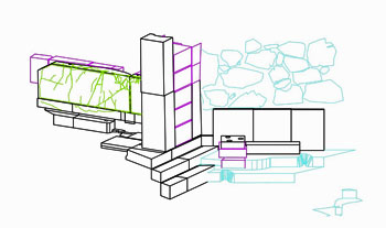
We need here a real-world example to illustrate the needs of archaeologists as they apply names to CAD layers. Since the CSA system for dealing with layers was developed to deal with the remains of the older propylon on the Athenian Acropolis, that example will be used here.
There were multiple phases, not only multiple phases of the pre-Classical entrance but material from the Bronze Age included in those more recent entrances. Some of the blocks were in situ; others had been moved either for re-use in a new location or simply by pressure from surrounding blocks over time. In addition, there were blocks of marble and limestone as well as carved surfaces in the native bedrock. There were also carefully shaped blocks for use in ashlar walls and less precisely shaped blocks used in the Cyclopean masonry of the Bronze Age. [That comment ignores the reasonable argument that Cyclopean masonry required a different but equally careful and precise shaping of blocks.] There were also blocks that had been re-worked, broken, or drilled at a date after their installation. There were reconstructions offered by various scholars, and two of those were included (my own and William Bell Dinsmoor, Jr.'s). There were parts of the model that were not really parts of the entrance but of the Mycenaean fortifications or later ramps. As if this is not enough complexity, there were also different kinds of CAD entities; some blocks could be modeled in 3D as groups of visible surfaces; others, the blocks in Mr. Dinsmoor's reconstruction, could not even be modeled as surfaces; only plan-level (2D) information was available. Finally, there were various miscellaneous items: a north arrow, a scale, explanatory text, and even a copyright statement.
As should be obvious, the complexity of the older propylon required a very large number of layers. In this instance, for example, most blocks had to exist as both 2D and 3D objects so that they could be used with either the 3D model from my own examination or the 2D reconstructions taken from Mr. Dinsmoor's publication. So there needed to be layers that had 2D plans and layers with 3D models -- of the same blocks. There also had to be ways to separate real blocks remaining in situ from my reconstructions from Mr. Dinsmoor's reconstructions from reconstructions agreed to generally.
In the end, it had to be possible, for instance, to select for some specific action all the CAD entities in 3D showing marble blocks of the first phase with Bronze Age material surviving into that phase and the portion of the entrance ramp thought to have been in use at the same time. It might also have been desirable to include or exclude a given scholar's reconstructed additions to the in situ material. Creating layers to hold CAD entities in such precise groupings that such selections are possible is not a trivial task. Doing to in a way that permits easy identification of the layers required for a given purpose is even more difficult. That is the task explored here. (Readers should also access this CSA Newsletter article for a somewhat different approach to the same issue: "Managing the Content of AutoCAD Models with Layers"), by Paul Blomerus and Harrison Eiteljorg, II.
The selection of the layer to be used for specific material -- and the name of that layer -- is at the discretion of the draftsman and may be entirely arbitrary. However, since there may be hundreds of layers for a complex model, the draftsman invariably uses a scheme of some kind to determine what is placed on each layer and to name the layers so that the contents of each will be clearly specified. Names must be meaningful but reasonably short to be useful.
A good system of layer-naming is important for the draftsman, but it can be even more important for others who use a CAD model to understand the material, site, or structure that has been modeled. Analysis requires not only managing the complexity of the model but being able to access specific parts of the model when needed. For instance, the model of the older propylon provided a truly revelatory moment when I suppressed the portion of the model containing material constructed of the soft local limetone called poros. It was suddenly clear that a portion of the marble remains must have been moved from its original location, because it was clearly isolated from the other marble blocks in a senseless way; the connecting blocks were the missing poros ones. That view of the model was only possible because the layer-naming system permitted it.
The layer-naming system presented here is intended satisfy both the needs of the draftsman and those of the other users of a CAD model. It is meant to be reasonably complete so as to provide a full and comprehensible example, but it is based on the needs of a specific architectural project, the older propylon model. As a result, it is not intended to be proscriptive. (A proscriptive system has been constructed by the American Insitute of Architects as a way to standardize CAD practices in the architectural design world.) It may or may not be applicable to any specific project, but it describes a framework as well as a complete system. While it is reasonably complete and should work for a wide variety of architectural projects, it may be more valuable as an example from which to create individual, tailored systems for projects of any kind. Even those for whom this particular system seems totally inappropriate should be certain that they understand the underlying principles. A good system, whether this one or some other very different one, will add immeasurably to the usefulness of a CAD model for the draftsman and the scholar. Whatever the system applied to a project, it must be documented if users are to be able to take advantage of it, and the documentation must accompany the CAD model as well.
The proposal outlined here is intended to aid in the process of naming layers and, more important, the process of retrieving layers according to sensible, systematic search criteria. When applied properly, the convention makes it possible to search for layers or groups of layers, quickly and efficiently, according to a variety of criteria (using the standard "wild card" characters - ? for any character in a specific location and * for any number of characters after the last specified one). It also provides a clear and understandable naming technique to permit quick access to individual layers -- without having to remember individual names.
The system is based on the searching potential of AutoCAD's standard layer selection processes. Whether using a dialog box or the command line, users can employ wild cards to select specific characters in layer names -- and to specify where in the name those characters will lie. The key to the flexibility of this system lies in the use of both the position of a character within a name and the character itself to provide meaning. Therefore, each letter in the layer name designates its information according to its position as well as the letter itself; an M in the first position carries a different meaning from an M in the fourth position.
The length of the names of the layers has been kept to a minimum - 8 characters for description plus ten characters for dates (or some other number of characters appropriate to an individual project). The eight characters for description make the system rather abstract, with single letters carrying complex meanings. The suggested scheme permits the letters of the alphabet and the numerals 1 through 9 (not 0) for the description. The dash/minus sign (not the underscore) and the numerals 0 through 9 may be used for the dates. Excavators may want to devise their own abbreviations for trench and stratum in place of the dates (but they should be aware of the limitations on character usage imposed by their own CAD system before setting out the abbreviation format).
Users should note that, as a result of confusion regarding basic character-encoding schemes in various computer systems around the world, CSA recommends using the basic (not extended) Latin characters for layer names. Although the system will work with any character set, the slow but steady shift to Unicode as the standard character set suggests that basic Latin characters should be used for layer names now. The reason for that is quite simple: basic Latin characters in ASCII, all the ISO character sets, and Unicode have the same numeric designations, and it is the numeric designations that are actually stored in data files. Other character sets will not keep their numeric designations in Unicode. Therefore, only basic Latin characters will provide a seamless migration path into the Unicode environment. (See "The Way Your Computer Handles Text is Changing," by Susan C. Jones, CSA Newsletter, XIV, 3 and "Unicode File Names: New CSA Policy," CSA Newsletter, XV, 1.)
The system described first is one that assumes an advanced level of analysis. It is not a system for an excavation still in progress, though the principles are the same. Discussion of an excavation system follows.
Coding the Dates
The dates are placed after the descriptive material, but the method for coding them is easier; so the date coding scheme is described first. For each layer there are two dates, one defining the earliest date attached to material placed on the layer and one defining the latest date. Therefore, layers may be selected according to either or both criteria. There are ten characters for dates, five for a starting date and five for an ending date (unused spaces must be filled with leading zeroes). Dates B.C.E. will include a minus sign in the first position. Dates in the common era have an extra leading zero. This permits dates only as far back as 9,999 B.C. using the minus sign, but there can obviously be no dates greater than 9,999 A.D.; so one may omit the minus sign from dates greater than 9,999 and assume that any date with a leading non-zero digit must indicate a year B.C. Therefore, the dates applied to layers can range from 99,999 B.C. to the present.
Dates must be entered as numbers in order to permit good searching; so dates which would normally be described in more general terms must be "rounded off." One form of rounding would be to omit trailing zeroes and code only decades, centuries, or millennia. The latter would be the likely choice for Paleolithic material, for instance. For later periods, rounding is more likely to require another approach. If a starting date is said to lie in the first quarter of the fifth century B.C., for instance, the date used in the layer name would be -0499 (499 B.C.). Similarly, something dated to the twelfth century would take 01100 to be the starting date and 01199 to be the ending date. Finally, in order to indicate material which is still in use, an ending date of 09000 should be used. An item erected in the first quarter of the fifth century B.C.E. and remaining in place today should thus use the following date code: -049909000.
Since these dates are not applicable until study has made them relatively secure, excavators should not attempt to apply them at the outset. Instead, they should use a group of characters that will designate unambiguously the available dating information. The coding will depend upon the individual project nomenclature.
Coding the Description
The specifics of the eight characters (preceding the date in the CSA system) for describing what has been modeled on a layer are as follows. There is no distinction between upper and lower case letters, since AutoCAD does not honor the distinction.
Character One, to indicate the kind of drawing, as opposed to the kind of archaeological material, on the layer -- or to indicate that the layer is used for artifacts:
A - Artifacts (icons representing artifacts in their appropriate positions)
B - Three-dimensional model of artifacts in their appropriate positions
C - Cracks or other damage to a 3D block or surface
D - Database links (see "Linking Text and Data to CAD Models," by Harrison Eiteljorg, II, CSA Newsletter, XIV, 3)
E - Explicit dimensions (as text or using AutoCAD's dimensioning features)
H - Holes or sockets in a 3D surface
L - Labels (text) for individual views or paper drawings
M - Modeled (3D) surfaces
N - Notes (The layer N, with no other characters, should contain a north arrow and the letter N only; for notes see "Linking Text and Data to CAD Models," by Harrison Eiteljorg, II, CSA Newsletter, XIV, 3)
P - Plan, two-dimensional-only drawing (lines, not surfaces)
S - Solid models
T - Texture (usually an indication of material or finish on a 3D surface)
Notes: Layers beginning with L may be treated differently than all others, since the labels may not apply to specific material but to specific views. As a result, the characters following the beginning L may describe the use of the label in a way useful only to the draftsman. Layers beginning with L may be excluded in the data file when it is transferred to a public data repository; the label layers may be intended only for paper drawings produced by the original draftsmen.
It may seem strange to have both plan and modeled layers, but the nature of 3D models of real-world objects often makes it necessary to have simpler plan views of 3D material drawn separately rather than trying to generate them from the three-dimensional model. There is too much irregularity and too much shifting of surfaces to permit good, clear plan views of complex three-dimensional models.
Character Two, to indicate whether the feature/object had been disturbed, was a random find, was found in situ at the point of last use, was found in situ but moved from its last point of use, etc.:
A - Not in situ but in general area of original, primary use
B - Not in situ but in general area of last but not original use
H - Hypothetical material that is uncontested
I - In situ, undisturbed at point of original use
J - In situ, undisturbed at point of last but not original use
K - In situ, disturbed at point of original use by natural disaster
L - In situ, disturbed at point of original use by man-made action
M - In situ, disturbed at point of original use by natural events subsequent to abandonment
N - In situ, disturbed at point of last but not original use by natural disaster
O - In situ, disturbed at point of last but not original use by man-made action
P - In situ, disturbed at point of last but not original use by natural events subsequent to abandonment
R - Random find
S - Natural bedrock
T - Trimmed bedrock
V - Virgin soil
X - Baulk
Z - Not relevant
# - A numeral used in this place indicates hypothetical material (the number should relate to a specific scholar or reconstruction so that layers may be grouped together by this number)
The third and fourth, fifth and sixth, and seventh and eighth characters are used in pairs to provide combined general (first character of the pair) and specific (second character) information about three categories - the area of the find, its usage, and the material.
Character Three, to designate the general type of the finding area, such as public area, domestic area, military area, work/manufacturing area, and so on:
A - Agricultural
B - Cemetery
C - Commercial
D - Domestic
E - Educational
G - Governmental
K - Mixed-use palace (one with substantial activities beyond the domestic or support for domestic)
L - Legal
M - Military
P - Public (intended to be a very general category)
Q - Palace (domestic & support use only)
R - Religious (sanctuary, shrine, etc.)
S - Athletic/sporting
T - Theater/entertainment
W - Manufacturing/work
Z - Not applicable
(The not applicable choice would be available for this and most positions, but it would be possible to have a clearly not in situ random find - according to the letter in position three - which was nonetheless found in a specific area.)
Character Four,, the specific part of the area, takes on a different meaning depending upon character three:
A - Anterooms in several areas, altar in religious areas
B - Barracks in military, burial in cemetery
C - Courtyard in most cases, cavea in theater
E - Entrance
F - Fortification in military, "retail" sales area in commercial or public, forge in a manufacturing/work area
H - General hall in a variety of areas
K - Kiln
L - Law court
O - Oven
P - Meeting place for governing body
R - Road or street
S - Surrounding wall in religious, stage in theater
T - Temple/church/shrine/mosque
U - Uncertain - indication that attribution in the previous character is uncertain
V - Hearth
W - Workshop
X - General, unstated
Z - Not applicable
Examples: Using MF as the third and fourth characters of a layer name indicates a military fortification; RT a temple, shrine, church, mosque, etc. in a religious area. WF indicates a forge in a work area; PR a road in a public area.
Characters Five and Six indicate usage (general and specific respectively), but they carry different meanings, depending upon whether the material is a movable artifact or not. The first of the two letters signifies a broad category - e.g., wall, column, or roof for a structure; weapon, cooking utensil, or tool for an artifact. The following character narrows the range of the first - e.g., base, drum, or capital for column; bow, knife, or point for weapon. The first character may also have a different shading of meaning depending upon the area designation, e.g., the floor of a kiln or oven is a very different thing from a building pavement, but both use the same character.
Character five, general use:
B - Buttress
C - Column (including cap & base)
D - Pillar/post
G - Gate
M - Monument (free-standing statue, stele, tripod, fountain, etc.)
P - Pavement/floor
R - Roof
S - Stair
T - Entablature
W - Wall
X - General
Z - Not applicable
Character Six, specific use, will take on different meanings according to character five:
B - Base for column or pillar; balustrade for stair; block for wall
C - Capital for anta or column, cornice for roof, core for wall
D - Drum for column door for wall
E - Euthynteria
F - Foundation
G - Fountain
H - Mosaic on pavement, fresco on wall
J - Joint or jamb
M - Molding or decorative addition (a broad category for embellishments which are not structural - mutules, guttae, antefixes, etc.)
O - Orthostate
P - Paver
R - Rafter for roof, retaining for wall
S - Step (including riser and tread) for stair, stele for monument
T - Tile for roof, tripod for monument
U - Uncertain - indication that attribution in the previous character is uncertain
V - Veneer for wall
W - Window
X - General
Z - Not applicable
Examples: Using MFWW as the third through sixth characters of a layer name indicates a window in a wall of a military fortification; RTCB the column base of a temple in a religious area.
Characters Seven and Eight indicate the material of the feature/object. Once again, a general category is given by the first of the two characters and a more specific one by the second.
Character seven, general material:
A - Animal Fiber
B - Building stone (cut or carefully shaped)
C - Concrete
D - Bone/ivory
E - Unbaked clay
M - Metal
P - Plant fiber
R - Rough stone (used without careful shaping)
S - Worked stone (for tools not building)
T - Terra cotta
V - Mudbrick
W - Wood
X - Bedrock
Z - Not applicable
Character eight, specific material, will take on different meanings according to character seven:
O - Oak for wood, obsidian for worked stone
P - Pine for wood, Pentelic marble for building stone, papyrus for plant fibers, lead for metal
S - Spruce for wood, sheep/goat for animal fiber or bone, steel for metal
U - Uncertain - indication that attribution in the previous character is uncertain
W - Wool for animal fiber, willow for wood
X - General
Z - Not applicable
Discussion
It should be noted that some material may exist on more than one layer. For instance, a triglyph found in a disturbed area would be drawn in its findspot on a layer identified by its findspot, usage, material, the dates applied to its excavation level, and so on. It could also be drawn on another layer identified by the date of the structure from which it is thought to have come, its use in that structure, and its material - and located where it would originally have been. That layer would, however, be identified as hypothetical, either associated with a specific scholar (therefore having a numeral in the second position) or taken to be generally accepted (and therefore having an H in the second position).
There are two matters that require further explanation. First, the inclusion of layers for artifacts may be unnecessary due to the emergence of linked relational data bases. It may be possible to keep control of artefacts and to insert icons representing their positions into the drawings without actually maintaining them in the drawing itself. However, given the proprietary nature of the links to relational data tables, it is probably better not to use those links and to follow a system such as the one described in "Linking Text and Data to CAD Models" in the CSA Newsletter, XIV, 3.
Second, in the paired characters, there are fewer and less inclusive suggestions for the second character in each pair. It is desirable to retain reasonable flexibility; so scholars should tailor the second character in each pair to their own unique situations, even if otherwise using this system as it stands. No matter how closely an individual iteration of this system follows the scheme laid out here, individual scholars must provide full explanations of their own unique systems, and that explanation must become a part of the documentation that accompanies the CAD files permanently.
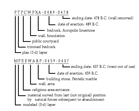
Two examples of layer names from a model of the Acropolis entrance:
A Layer Naming System for Excavation Models
The layer-naming scheme described above is an analytic scheme and many of its specifications will not work well for excavations that are in progress. Too much of the final analytic process is presupposed by the system; in addition, it is unrelated to excavation processes, trench locations, excavation dates, etc. As a consequence, most excavators need a different system, one that separates material according to excavator, season, trench, and the like. Applying the same principle of using both the character and its position in the name, a system appropriate for any excavation can be worked out -- and documented.
An excavation system might include the year of the work (four characters) followed by a trench indicator (number of characters determined by the project's nomenclature), followed by the locus designation (also with the number of characters determined by the nomenclature), followed by other information considered important by the excavator. Thus, 2002NT10045 . . . indicates trench NT, locus 10045, of the 2002 excavation season.
As analysis progresses, the excavation scheme might be replaced by the analytic one. It is better, however, to maintain both schemes simultaneously. This is now possible with AutoCAD, because the search routines have become more flexible. Specifically, the search routines permit the user to use the asterisk (*) as a wild card with letters after as well as before. That is, searching for layer *8 will now work to find all layers ending in 8. (In earlier versions of AutoCAD, the asterisk was treated as the final character in any search string; anything following was ignored. Thus, *8 would have been equivalent to * and all layers would have been identified.)
Using AutoCAD's current searching capability, two naming systems can be used for the same layer with a marker to separate them. One part of the layer name is the excavation scheme, and the other is the analytic one. Using the separator, the user can perform complex searches with either system and with no knowledge at all of the other. Of course, the operator could also use both systems for even finer discriminations. (Using such a double system will almost certainly require breaking exising layers into multiple layers, since it is unlikely that each layer in an excavation system will correspond precisely with a single alalytic layer.)
For instance, consider the excavation system defined above (stopping at locus name). If that system were the original layer-naming system and the analytic one described above were then grafted it in the course of the analysis, with an underscore between, one might have a layer name such as 2002NT10045_PTPCWFXA-0489-0478. The characters before the underscore show excavation information: year, trench, and locus; the characters following the underscore provide the analytic information. Searches using the asterisk can be made with either system. A search pattern for the first characters that concludes with an asterisk would ignore the last 19 characters (including the underscore). A search pattern beginning with *_ and following with a pattern based on the analytic system would ignore the excavation system. Thus, either system could be used independently. Of course, complex searches could be done with search patterns taking advantage of both systems at the same time.
Layer Names with Multi-File Models
When models become too large and/or complex to be treated within a single CAD file, most CAD programs, including AutoCAD, permit users to relate other files to a base file so that each can be used alone or all can be used together. As a result, the entire model can be seen and queried, but smaller individual parts can be modeled in isolation. In AutoCAD parlance, the base file is said to reference external files, which, in turn, are said to be x-refed to the base file. (Entities placed on a layer in an external file are not individually accessible. The selection of any entity modeled in an external file is considered to be the selection of all the entities from that external file.)
Layers in all the files are still individually accessible, but the layer names must be more complex. One might easily have the same layer on more than one of the external files linked to a given base file. Therefore, the external file name is treated as a part of the layer name for each layer from an external file. That is, when using a base file with external files referenced, the external file layers are named with the file name plus the vertical bar symbol (|) plus the layer name (no spaces). Thus, the layer named above, 2002NT10045_PTPCWFXA-0489-0478, if in an external file named "exfile," would be perceived by AutoCAD as being named exfile|2002NT10045_PTPCWFXA-0489-0478. The presence of the vertical bar symbol provides the same kinds of searching possibilities as the use of the underscore in the previous discussion of a dual-system layer-naming scheme. It is possible to select layers according to broad categories -- the file name, for instance -- or very narrow ones, and the narrow ones can apply to layers in all external files at once. A search for *|*_PTP*, for instance, would find all external-file layers beginning with PTP in the analytic scheme, but that specification would omit all layers in the base file, since those layers would not have the vertical bar in their names.In a complex set of files that compose a single model, the files need well-considered names just as the layers do. Therefore, a system similar to the layer-naming system should be used -- and documented -- for the file names. It is unnecessary to lay out such a system here in the abstract, but characteristics similar to those used for layer names should be included. (For an example of a file-naming system, this one for the CSA Propylaea Project, see the CSA Newsletter, XV, 1, "Multi-File CAD Models.") The file-naming system, like the layer-naming one, should use basic Latin characters for the sake of the ultimate translation into Unicode.
Users of multi-file models should also be wary of using a base file that contains part of the model. CSA recommends that the base file be empty, save for a layer with a scale, a layer with the north arrow; the zero (0) layer, which cannot be removed from an AutoCAD model; and a layer to which the external files are attached. (All external files are attached to a specific layer in a file, not the file itself.)
There is one more issue with multi-file models to be discussed, though it is only peripherally related to layer names. When external files are referenced by an AutoCAD file, AutoCAD's default settings assume a networked environment and therefore assume an explicit directory structure along with the file names. As a result, the typical external file is seen as lying in a specified directory within a specific directory superstructure. Since scholarly CAD files are intended to be copied from an archive by various users, the directory structure will not remain constant for subsequent users. As a result, the program will not find the referenced files automatically. However, referenced files can be given relative rather than absolute directory locations, and such names will provide automatic access when a group of files has been moved into another directory structure, provided only that the directories used for the base file and the external files remain in the same relationships to one another. The process of using relative directory names is explained in the AutoCAD manual.
- Title: CSA Layer Naming Convention
- Author: Harrison Eiteljorg, II and the staff of CSA, Box 60, Bryn Mawr, PA 19010 (email: user-name nicke at (@) domain-name csanet.org; tel.: 484-612-5862)
- File name: csalnc.html
- Revision history: This is the third electronic version of this document. The third revision involved only the introductory text, and the author is very grateful to Paul Blomerus, whose thoughtful comments led to this revision. It is not deemed to be a preliminary publication, and there are no plans for further revisions; should revisions be made, however, this version will remain available at the CSA Web site under the name csalnc.html or a successor name; posted September, 2009. The previous version of this document may be found at http://csanet.org/olderversions/csalncsept2009.html.
- The only illustrations used in this document should need no revision unless the document is revised. Corrections of typographic errors will not be noted.
- Review process: The document has not been subjected to prior peer review but has been revised regularly after consultation with and recommendations from other scholars.
- Paper publication history: Articles about the CSA Layer Naming Convention were written for the CSA Newsletter -- first version in the issue for May, 1988 (I, 1: "Layer Naming Conventions Important in CAD"); revised in the issue for November, 1989 (II, 3: "Preliminary Proposals forArchaeological Layering Convention"); further revised in November, 1990 (III, 3: "Layering Standards - Some Changes"); revised again in February, 1991 (III, 4: "Layer Naming Convention - Again"); extended in May, 1991 (IV, 1: "Layer Names for Excavations"); revised in February, 1993 (V, 4: "Layer Names Again"); revised further in the Fall, 2000, issue (XIII, 2: only available on the Web "New Searching Possibilities for AutoCAD Layers"), modified implicitly in the Winter, 2002, issue (XIV, 3: only on the Web, "Linking Text and Data to CAD Models"), and last modified in the Spring, 2002, issue (XV, 1: only on the Web, "Multi-File CAD Models"). An article describing ways to use the layer names in an external database or spreadsheet appeared in the September, 2009, issue (XXII, 2: only on the Web "Managing the Content of AutoCAD Models with Layers," by Paul Blomerus and Harrison Eiteljorg, II. This electronic version is based on the entire sequence of prior articles, with minor appearance modifications added 19 March 2010 and other changes to the appearance necessitated by the re-design of the CSA web site in August of 2010 (involving no change to the text).
- Internet access: This document is maintained at csanet.org by CSA and Harrison Eiteljorg, II. Note that there may be changes in computer addresses that are beyond the control of CSA.
- Long-term availability: This document and/or its successors will be maintained for electronic access until the technology makes the information useless. When it is no longer directly accessible, it will remain in the CSA archive.
- Citation permissions and copyright information: This document is copyrighted by CSA. Citations should include the date of the document cited. The document may not be reproduced without the explicit permission of CSA. However, CSA will readily grant free use for scholarly purposes.
- Internet access: This document is maintained at csanet.org by the Center for the Study of Architecture and Harrison Eiteljorg, II. Note that there may be changes in computer addresses that are beyond the control of CSA.
- Long-term availability: This document or its successors will be maintained for electronic access indefinitely. Prior versions will not be archived.
- Citation permissions and copyright information: This document is copyrighted by CSA. Citations should include the date the document was accessed.