
|
 |
 |
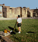
| Fig. 1 - Mr. Hanna at the total station in the Eumachia Building at Pompeii. |
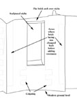
Fig. 2 - Hidden line drawing of portion of west interior wall, Eumachia building. See Fig. 1, at left, for a photograph of this wall. |
The 1996 season at Pompeii was quite different from the 1995 season. Photogrammetry was not used, and the remains surveyed all were within reach of someone on the ground or on a ladder - with the help of our fishing pole and remote target. As a result, each day's survey data could be downloaded from the data collector, and there was no need to wait until a later time to turn the data points into parts of a computer model. That, in turn, encouraged us to transfer each day's survey data into the computer and to create the relevant portion of the model from that data before going back into the field. We couldn't have kept up with the data if we had surveyed all day, but we learned that data from four or five hours of surveying in the morning could generally be turned into parts of the model after about the same amount of time working with the computer in the afternoon.
The results of this way of working - spending the time from about 8 a.m. until noon or 1 p.m. in the field and the afternoon and early evening in the "office" making the model - were a small data backlog and a much greater sense of the pace of the work as themodel grew.
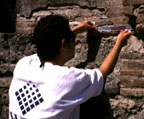
Our work was also helped by the survey aids that had been made before leaving for Pompeii. The acrylic plate used to position the prism - either the standard prism or the mini-prism - came in very handy. It was much easier to resurvey precise points that had been surveyed before and to be certain that the prism lay in the same position each time we returned. It was also easier to position a prism directly over the corner of a stone, even if the stone had been abraided.
The target that was made this year to attach to the fishing pole turned out to be even more valuable than we had expected. That target was simply a clear plastic ruler with reflecting tape on its back surface. A clamp to attach it to the fishing pole was included but could be completely removed. Both red and gray reflecting tape were used, and the tape was positioned so that the color changed at points 10 cm. and 20 cm. from the tip of the ruler, and the tape stopped at the 30 cm. mark. That made it possible to take two readings, neither of which was at the tip of the ruler but both of which lay on a line a known distance from the tip (10 cm., 20 cm., or 30 cm. from the tip). Those readings could be taken even if the instrument was quite a distance from the target.
 |
 |
The target worked well on the fishing pole as well, making it possible to take readings of points very far off the ground. Indeed, on one occasion, I was unable to see the points as I was maneuvering the fishing rod and target. My movements were guided either by Mr. Hanna or Project Director John J. Dobbins until the position of the reflecting tape was correct. Then the reading could be taken.
We did have a problem with our software this year. The process of sending data from the data recorder to the computer did not work correctly, though we were able to find a work-around. That was distressing, and we have not determined the nature of the problem. Part of the problem may be related to the use of Windows NT on a laptop, since the program cannot find the serial port when the computer is away from the office.
For other Newsletter articles concerning the applications of CAD modelling in archaeology and architectural history or Pompeii, consult the Subject index.
Next Article: Easier Web Access
Table of Contents for the August, 1996 issue of the CSA Newsletter (Vol. 9, no. 2)
 Table of Contents for all CSA Newsletter issues on the Web