 |
Harrison Eiteljorg, II
The work on the CSA Propylaea Project has been continuing, and the potential for using a spreadsheet to help has been found to be even greater than had been reported earlier in a Newsletter article about the advantages of using a spreadsheet to create AutoCAD commands (v. IX, no. 1; Spring, 2000, "Using a Spreadsheet to Speed AutoCAD Data Entry," Harrison Eiteljorg, II; http://csanet.org/newsletter/spring00/nls0004.html). Two new and expanded applications of the same general idea have been found to add substantially to the convenience. (Many readers will recognize that the same techniques could be used with a database program.)
The first of these extensions to the usefulness of spreadsheets builds directly on the prior work. In the previous article a spreadsheet was described that permitted the data (x-, y-, and z-coordinates) for the north wall of the NW wing of the Propylaea to be typed into the spreadsheet as a base from which blocks were drawn. Other cells in the spreadsheet used formulae to generate AutoCAD commands using the coordinate information; the commands could be cut and pasted directly into the AutoCAD command line. A great many simple faces could be drawn by copying the command string and pasting it into AutoCAD. Not only could many faces be drawn with a single copied command string, bur errors in the formulae could be found and repaired without requiring lengthy and error-prone re-entry of coordinate data. The gain in efficiency was significant.
| 7 | UL | 1.7095 | 0.3520 | 5.0970 | 1 | 3DFACE 1.7095,0.352,5.097 |
| UR | 2.9665 | 0.3600 | 5.1050 | 2 | 1.7165,0.3535,4.291 | |
| LR | 2.9720 | 0.3600 | 4.3005 | 4 | 2.972,0.36,4.3005 | |
| LL | 1.7165 | 0.3535 | 4.2910 | 8 | 2.9665,0.36,5.105 |
The first column contains the block number; the second column indicates which corner of the block is being defined in the row. The next 3 columns contain the x-, y-, and z-coordinates. The following column has a number to indicate whether or not the coordinate data are complete for that corner; the total of this column for the four corners will be 15 only if all corners are specified. The final column contains the AutoCAD command, beginning with "3DFACE" and continuing to the final number, 5.105; however, that column is only filled if the total of the four values in the sixth column is 15. Careful readers will note that the coordinates are not ordered as one might expect. That is because clockwise progression around a block seemed natural for data entry, but making the surface with that order would create a problem with the surface orientation; see: CSA Newsletter, v. XIII, no. 3; Winter, 2000, "A Subtle CAD Problem -- The Surface Normal," Harrison Eiteljorg, II; http://www.csanet.org/newsletter/winter01/nlw0107.html. Therefore, the input order permits clockwise data entry -- upper-left, upper-right, lower-right, and lower left -- but the command uses the order necessary to create the surface with the proper orientation -- upper-left, lower-left, lower-right, and upper-right. This is one of the advantages of using the spreadsheet to do data entry. The entry of data into the spreadsheet can be in the order that seems best to the user, while the actual entry of data into AutoCAD is in the order required by the program.
When the process was complete, however, there were many blocks for which one or more dimensions were missing. Generally speaking, the missing dimensions were those needed for broken corners of the blocks.
Since there were so many missing dimensions, a large number of the blocks could not be drawn. The only way they could be drawn was by making assumptions about the coordinates of the missing/damaged corners. Using the drawing of the wall and the information in the spreadsheet, it was possible to generate additional formulae that would provide missing coordinates. Simple rules were used to determine the missing numbers. For instance, a missing corner elevation might be taken from its nearest neighbor or a depth might be taken from other portions of the same block.
| 1 | UL | -5.863 | 0.3655 | 5.0915 | 1 | -5.863 | 0.3655 | 5.0915 | 1 | 3DFACE -5.863,0.3655,5.0915 |
| UR | 5.095 | -4.5735 | 0.355 | 5.095 | 2 | -5.867,0.3725,4.289 | ||||
| LR | -4.5735 | 0.355 | 4.2885 | 4 | -4.5735 | 0.355 | 4.2885 | 4 | -4.5735,0.355,4.2885 | |
| LL | -5.867 | 0.3725 | 4.289 | 8 | -5.867 | 0.3725 | 4.289 | 8 | -4.5735,0.355,5.095 |
Fig. 2 Block 1 from the spreadsheet. (Two coordinates are missing for the upper right corner; so the spreadsheet automatically entered the values from the lower right corner. Then the AutoCAD command could be constructed as before.)
Of course, it was also necessary to show the broken shapes of blocks; so the missing dimensions were usually needed only to provide data to model the stones before they were damaged.
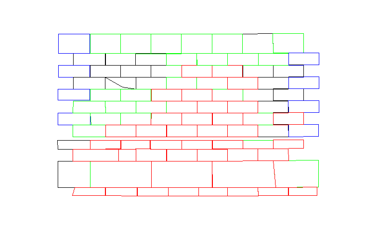
The result is valuable in two ways. First, many more of the blocks could be drawn (on their own layers to separate them from the blocks for which the original data were adequate). Indeed, using formulae to fill in the missing information, it was possible to define nearly all the blocks, as shown in Fig. 3. (The thin "string course" could not be properly defined; so it is missing. The first course above the floor also could not be included with this process.) Second, the method for filling in missing information is explicit. That is, the formulae that were used show clearly what assumptions were made in each case; so anyone can check to see what assumptions were made to model any particular block.

Fig. 3 North wall of Propylaea NW Wing, as modeled with implied dimensions, via the spreadsheet. Different colors indicate different formulae for supplying missing data. Note that the lower left corner of the second block from the left on the fourth row from the top seems to have been modeled incorrectly. It was. The coordinates on the drawing were in error, something that only became apparent when the CAD model was created and another drawing generated from it. (The north wall as modeled previously, without added coordinates was illustrated in a previous article. The second block from the right in the top course is the one marked with an X in the previous model.)
This method was used first on the north wall of the NW wing of the Propylaea, but it may be applied to other walls as appropriate.
The other extension to our use of a spreadsheet was created to help CAD technicians deal with complex data entry for surfaces. AutoCAD surfaces -- not just AutoCAD surfaces but surfaces in any CAD program -- require very painstaking data entry procedures. Ironically, the data entry procedures can be more difficult for making surface models than for making solid models, even though solid models are more complex. Spreadsheets can easily be used to hold coordinates for a number of surfaces, with the commands being automatically generated. The saving can be considerable if there are enough similar shapes being drawn.
The root problem is that CAD programs have no simple way to deal with irregular surfaces that are nearly, but not quite, flat planes. Indeed, there are no easy ways to deal with the geometry of such surfaces.
Modeling these surfaces is time-consuming and error-prone. Coordinates must be typed at the keyboard, and errors are truly exasperating, since they require re-entry of data from scratch. Not only that, but the order of data entry is crucial for the sake of surface orientation, as mentioned above.
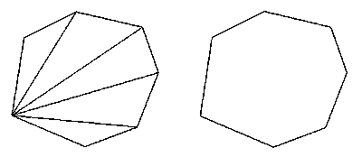
Using a spreadsheet (or a database program) makes it possible to automate part of this process. The result is a saving of time and frustration as well as something coming close to what is called parametric modeling -- creating parts of a model with processes that can be altered after the fact so as to adjust the model. The spreadsheet will not enable true parametric modeling, because it will not modify the model itself by simply changing one of the entries in the spreadsheet. However, it will permit individual model parts to be re-created with new numbers or new command sequences without requiring all the information to be re-typed. A new command sequence need only be copied and pasted into AutoCAD to re-create the items with new parameters. Of course, the prior versions of the modeled objects must also be erased. The spreadsheet routine shown here assumes an n-sided figure (up to 15 sides, but the spreadsheet could easily be modified to permit more), with each individual plane to be triangular in shape, and each connected to the starting point, as in Fig. 9.

Fig. 9 A seven-sided surface modeled from data entered into a spreadsheet. The version to the left shows all joints between surfaces, and the version to the right shows the figure as actually modeled, with invisible joints.
The relevant part of the spreadsheet is shown here, in Fig. 10.
| pnt. | x | y | z | x,y,z | x,y,z at once | x,y,z for formula | command |
| 1 | 114.34 | 117.97 | 0.016 | 114.34,117.97,0.016 | 114.34,117.97,0.016 | ||
| 2 | 156.604,99.879,-.018 | 156.604,99.879,-.018 | |||||
| 3 | 186.793 | 111.186 | -0.015 | 186.793,111.186,-0.015 | 186.793,111.186,-0.015 | 3dface 114.34,117.97,0.016 156.604,99.879,-.018 i 186.793,111.186,-0.015 | |
| 4 | 198.868 | 142.846 | 0.005 | 198.868,142.846,0.005 | 198.868,142.846,0.005 | 3dface i 114.34,117.97,0.016 186.793,111.186,-0.015 i 198.868,142.846,0.005 | |
| 5 | 189.812 | 169.229 | 0.034 | 189.812,169.229,0.034 | 189.812,169.229,0.034 | 3dface i 156.604,99.879,-.018 198.868,142.846,0.005 i 189.812,169.229,0.034 | |
| 6 | 151.321 | 178.275 | 0.154 | 151.321,178.275,0.154 | 151.321,178.275,0.154 | 3dface i 186.793,111.186,-0.015 189.812,169.229,0.034 i 151.321,178.275,0.154 | |
| 7 | 121.132 | 163.199 | 0.123 | 121.132,163.199,0.123 | 121.132,163.199,0.123 | 3dface i 198.868,142.846,0.005 151.321,178.275,0.154 121.132,163.199,0.123 |
Fig. 10 -- The portion of the spreadsheet used to draw the surface in Fig. 9. Numbers could be entered as either individual coordinates (point 1) or as three-coordinate specifications (point 2). They had to be be entered in the proper order (for correct surface orientation). The figure was then constructed by copying the text in the final column and pasting it into the AutoCAD command line.
The use of spreadsheets as aids to data entry in AutoCAD will not solve major problems, but it can make the construction process quicker, easier, and less error-prone. It can also provide an excellent source to accompany documentation, showing how surface information has been generated.
-- Harrison Eiteljorg, II
To send comments or questions to the author, please see our email contacts page.
For other Newsletter articles concerning the Propylaea Project, applications of CAD, or the use of electronic media in the humanities; consult the Subject index.
Next Article: A New Web Host for CSA
Table of Contents for the Fall, 2001 issue of the CSA Newsletter (Vol. XIV, No. 2)
 Table of Contents for all CSA Newsletter issues on the Web
| Propylaea Project Home Page |
CSA Home Page |