
|
|
|
Some Locally Adaptive Tone Mapping Methods for Color and Exposure Error Correction
Irwin Scollar, Remagen, GermanyA large number of color and gray-scale images made on film material, and a considerable number made with digital cameras have both color, brightness, and contrast problems which make archaeological features difficult to see or reproduce adequately on a display or a printer. Many methods are available for correction in conventional photographic software packages, but often these require a lot of hand labor. Those which use multiple images at different exposure levels are unsuited for hand-held cameras or moving objects. This article will discuss single-image treatment methods which, given the capabilities of modern digital and film cameras, are usually adequate.
Fully automatic correction techniques are not possible, given the variation in image sources and data obtained under all imaginable conditions, but a number of methods are available which can be of great assistance.
First, a brief review of image production compared with the working of the human visual system is offered. Then, some of the methods available are reviewed, and finally a number of results are presented.
Sensors:
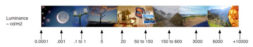
Fig. 1 - Luminance range of natural scenes.
From a night sky to direct sunlight, the luminance of a natural scene can range from 0.0001 to 10,000 candelas per square meter. Human vision is capable of adapting to large portions of this enormous range, with reasonably constant colors perceived. Images made with digital or film cameras do not have the adaptation capabilities of the eye and brain. Colors or gray-scale values either saturate at high luminance levels or are indistinguishable at low values. Output devices including printers and displays have far lower dynamic range than film, digital sensors and human vision; so mapping of the data from the sensor which reduces the dynamic range without losing information is required.
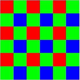
Fig. 2 - Bayer color filter array.
The silicon digital sensor used in most digital cameras contains a uniform array of CCD or CMOS pixel sensors covered with a filter invented by Bryce Bayer at Eastman Kodak in the 1970's and which bears his name. These filters limit the spectral response of each diode to either the red, green, or blue region. Exceptions are the Foveon sensor used in Sigma cameras which has the elements stacked vertically, or in the Fujifilm S5 Pro which has sensors of two different sizes and sensitivities in order to increase the dynamic range. The Bayer pattern may differ slightly between various sensor manufacturers, but there are usually more green than red or blue sensors.
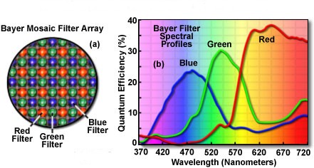
Fig. 3 - Microlenses + Bayer array, Spectral Response.
Each sensor element is covered by a microlens which concentrates the light coming from the camera lens. The color of a pixel of the output image in consumer grade cameras is the response of all the sensors in a small area transformed by the camera's internal processor into JPEG output. So-called RAW output from professional cameras contains the values of the individual sensors' responses to the colors of the filters above them, and processing is done by external software, usually to make a file in Tiff format.
At high light levels, sensors saturate and produce no further output. At low levels, statistical fluctuations in the number of photons intercepted by the sensor limit the accuracy of the necessary conversion to digital form. The larger the physical area of the sensors at each pixel, the more photons can be intercepted and the effect of fluctuation is reduced. Hence the ratio of output signal to photon fluctuation noise and the resulting dynamic range of the sensor between high and lowest light levels depends on the physical area of the CCD or CMOS array divided by the total number of pixels. For constant physical sensor size, larger numbers of pixels (the megapixel number) reduce the dynamic range available. Smaller sensors are cheaper to produce; so consumer grade cameras have much smaller sensors than do professional cameras. Hence their dynamic ranges are lower, and in dark areas, information is not recorded.
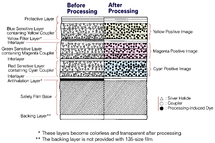
Fig. 4 - Transparency film layers.
Modern color films have a complex structure of nine or more layers containing blue, green, and red sensitive silver halide crystals and dye couplers along with filter and antihalation layers. The sensitivity to light of a given layer depends upon the grain size distribution of the crystals, the larger ones being able to intercept more photons and thus respond to lower illumination levels. Some films even have two layers for each color with different grain size distributions in order to increase their dynamic range. The signal-to-noise ratio depends on the graininess of each layer. As a rule, the dynamic range of film is less than that of a professional grade digital sensor. However, saturation at high light levels is also less so that the total light range covered may be greater, but given the signal-to-noise ratios, the total dynamic range after digitization is nonetheless lower.

Fig. 5 - Comparison of dynamic ranges of a high-end camera and a professional film with thanks to Roger N. Clark for permission to use this graph.
Films must be scanned if used for digital processing, and the optical and geometric properties of the scanner used introduce some additional limitations on the resolution and dynamic range of the resulting images. Optical enlargement and chemical paper printing introduce further reduction in dynamic range.
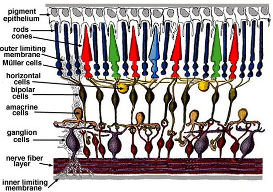
Figs. 6A & 6B - Cross-section and front view of an idealized retina.
Considered as a sensor, the retina is composed of two main layers, the inner plexiform layer (IPL) which is the location of the synaptic triad of cone, horizontal, and bipolar cells, and the outer plexiform layer (OPL) where bipolar, amacrine, and ganglion cells communicate. In these layers, horizontal and amacrine cells have a role of horizontal connectivity, where bipolar cells transmit signals from the IPL to OPL. Cones sample light and ganglion cells transmit information to the visual cortex. Along with the contraction and expansion of the pupil which alters the light coming from the lens, this complex structure can adapt to different light and color levels far more subtly than any film or digital sensor.
Algorithms for locally adaptive processing of high dynamic range (HDR) images
Most HDR algorithms are based on human visual system models models which simulate the local adaptation that occurs while the eye views a scene.
Classical Retinex:
The earliest, dating from 1964, is due to Edwin Land, the inventor of Polaroid, which he named Retinex, combining "retina" and "cortex." He tried to understand how the human visual system achieves color constancy over such a wide range. In the Retinex model, the ratios of the relative intensities in the color channels are kept constant under changes in illumination.
Multiscale Retinex:
Introduced by Thompson, Rahman, and Park in the 1990's, this improved model uses two intensity surrounds for each pixel and is fairly quick to calculate, but it introduces artefacts at the edges of large constant areas and saturates at high luminance levels. It is used in a number of commercial picture processing programs.
Adaptive Brightness/Contrast:
A simple model based only on local brightness and contrast was introduced by Wallis in the mid 1970's which, given the slow computers of the day, was much easier to calculate. It too introduces computational artefacts at sharp edges, but its computation is the fastest of all methods for very large images. Some unavoidable sharpening is also introduced.
Automatic Color Equalization:
Rizzi, Marini, and Gatta published a much more complex model for Automatic Color Equalization in 2003. ACE is an algorithm for digital image enhancement with simultaneous local and global effects. It uses a lateral inhibition mechanism as well as a local global contrast in order to approximate the visual appearance of a scene. The model tries to combine those two mechanisms. Within the model, each basic principle is considered as part of a unique adaptive behavior involving the contribution of each mechanism to the final result. Each mechanism has a local and a global effect resulting from simple local interaction between pixels within the image. In fact, the model performs a lateral inhibition mechanism, weighted by pixel distance resulting in a local-global filtering on the image. This requires considerable more processing time compared with other methods in exchange for very good results.
Adaptive Tone Mapping (MAS):
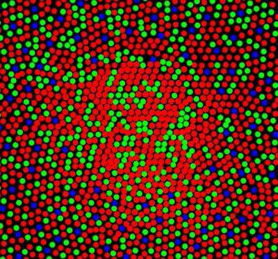
Meylan, Alleyson, and Süsstunk published a locally adaptive algorithm in 2007 which is based on a simple model of retinal processing, consisting of a mosaic of chromatic samples on which they apply two non-linear adaptive processes representing the IPL and the OPL (see figure 6A).
In the program Lumincor, the author applied it only to luminance, and using fast methods for the two smoothing steps made it even faster to calculate for large images. It produces results which are almost as good as the ACE method. It does not introduce any computational artefacts, but it does require subsequent gamma and saturation correction, both of which are very quickly calculated.
Programs:
All four algorithms are implemented in the author's CastCor (version 1.12 or later) and AirPhoto (version 3.28 or later) programs. His Lumincor program has the MAS method in a convenient stand-alone framework. This new method will be described here in greater detail.
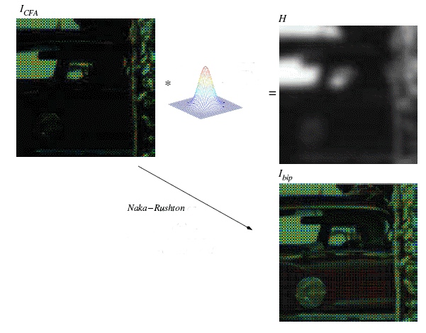
Fig. 7 - Raw image, Gaussian filtered, followed by a non-linear step.
Either RAW or data from camera processed JPEG, TIFF or other formats is first separated into luminance and color components. The luminance component is smoothed with a fast Gaussian blur algorithm and then an unusual non-linear operation is applied.
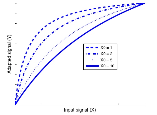
Fig. 8 - Naka-Rushton adaptive output for various luminance surround levels.
This non-linear processing step is based on an analysis made by Naka and Rushton of the response of a fish retina to different luminance surround levels. For high luminance in the immediate surrounding area, the response is almost linear whereas for lower luminances in the surrounding area, the output is more and more non-linear. This enhances the data at low luminance levels as a function of the immediate neighborhood of each pixel.
Two applications of Naka-Rushton following the Gaussian filtered luminance with different degrees of blurring are calculated. The result is then recombined with the original color after giving it a fixed gamma correction. Finally, additional gamma correction may be applied, followed by saturation correction at the user's discretion.
Pre-treatment, white point correction and global brightness and contrast change:
Pre-treatment for most images is usually helpful for all four methods. Unlike digital cameras, film cameras do not correct for unwanted displacement of the white point of an image. Sometimes the automatic white point correction in a digital camera will be insufficient if lighting conditions are extreme.
Badly underexposed images may require a global shift in brightness in order to bring the color components into processing range to prevent clipping at low values. Some subsequent global contrast enhancement may also be helpful. These steps may also be applied to grayscale images, and the adaptive enhancement techniques are usually quite effective with them too.
Some results:
A 40 year old Kodachrome slide duplicate of a prehistoric site at Conchil-le-Temple in the Somme valley from Roger Agache had darkened considerably. It was scanned using a Microtek ArtixScan 4000T 35mm film scanner with automatic white and black point contrast correction. Applying an additional automatic whitepoint correction as pre-treatment in CastCor restored some of the original appearance. Then luminance correction was applied. The original from the scanner is shown on the left, the improved image on the right in the figure.
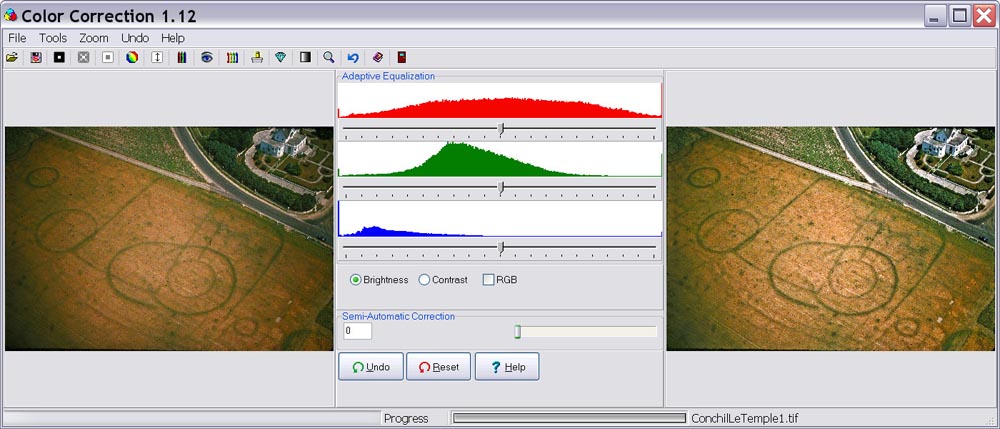
Fig. 9 - Auto-white followed by locally adaptive luminance correction.
The CastCor program used to treat this image offers an unlimited number of many different operations applied sequentially to a smaller sampled image for speed. When appearance is satisfactory and the image is saved, the changes are applied to the full resolution original.
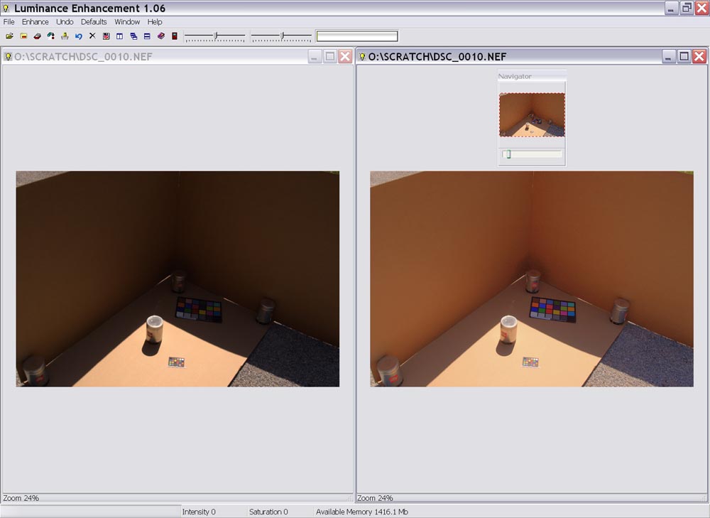
Fig. 10 - Image with luminance correction, default saturation & intensity.
A test image made with a Nikon D100 and using raw NEF output by CSA Director, Harrison Eiteljorg, II, subjected to luminance correction with default values greatly improves visibility in the dark areas without distorting colors or introducing edge artefacts. The Lumincor program used to treat this image permits simultaneous display of multiple images as well as batch processing of a user-chosen collection of pictures with the same correction constants.
-- Irwin Scollar
Bibliography
A good general survey of the tone mapping problem is:
The algorithm (MAS) used in Lumincor is a modified form of that described in:
The adaptation to wide-ranging luminance in Lumincor is based on a modification of the model from:
Further references available from the EPFL web site: ivrgwww.epfl.ch/publications/index.html including:
The MAS implementation in Lumincor, CastCor and AirPhoto uses:
Classical Retinex, see:
Multiscale Retinex methods are described in:
The ACE (Automatic Color Equalization) is described in:
The Wallis algorithm is described in:
Film, Grain and Lenses and their effects are discussed on many Web sites:
For an excellent general discussion of digital vs. film photography, see Roger N. Clark's web site: http://www.clarkvision.com
A good non-mathematical discussion of digital sensors is at http://learn.hamamatsu.com/articles/.
Programs:
The methods reported here are available in the following programs:
Acknowledgements:
Fabrizio Di Vittorio of HiComponents, Ladispoli, Italy, is hereby thanked for implementing and adding a fast version of the ACE algorithm of Rizzi et al. and the MRSCR version of the Retinex algorithm to the HiComponents package at the author's request.
Laurence Meylan, formerly of the EPFL, now of General Electric Research Laboratories, Lausanne, Switzerland, kindly placed her Matlab code at the author's disposal for porting to Delphi in Lumincor.
Rog Palmer of Airphoto Services, Cambridge, UK, is thanked for testing the programs and making suggestions for many improvements.
Joost van de Weijer of LEAR, Grenoble, called the author's attention to the Geusebroek implementation of fast Gaussian filtering and offered helpful advice on its application to the luminance problem.
For other Newsletter articles concerning the use of electronic media in the humanities, consult the Subject index.
Next Article: Website Reviews: stoa.org
Table of Contents for the Fall, 2007 issue of the CSA Newsletter (Vol. XX, no. 2)
![]() Table of Contents for all CSA Newsletter issues on the Web
Table of Contents for all CSA Newsletter issues on the Web