
|
There have been several articles in this Newsletter concerning the use of computers for illustrating pottery, most recently in the last issue, "Drawing Profiles - Another Method," by Harrison Eiteljorg, II, Feb., 1996, pp. 5-9). I also have been working on this procedure with Mr. Eiteljorg as part of a project to computerize the pottery drawings from the Tell 'Ein Zippori, Israel excavation for Professor J. P. Dessel of Bryn Mawr College. The pottery illustrations were hand-produced in the field with pencil on colored graph paper.
The method finalized by Mr. Eiteljorg and me was to scan the drawings into Photoshop to remove the graph paper background, bring them into Draftsman PLUS for vectorizing, (1) and eventually store them in AutoCAD as a database of illustrations available for comparison, reproduction, reconstruction, or a variety of other manipulations. I focused on the process of creating line drawings in the computer from the scanned images. While this process involved much more subjectivity on the part of the computer illustrator than I had assumed previously, I found vectorizing the scans in the Draftsman program much more suitable than digitizing directly into AutoCAD for dealing with a large number of drawings in the most timely, accurate, and comfortable manner.
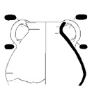 Fig. 1 - Profile drawing created with Draftsman (and output to Adobe Illustrator for the Newsletter).
After the scanning and general clean-up in Photoshop, Draftsman PLUS was the program used to vectorize the scanned image. This program had many commands and tools for adjusting the vector image, as some modification certainly was needed after the automatic vectorizing. The vectorizing often followed pixels that were not part of the main lines or arcs, creating double lines where only one should exist and short lines that spurred off the main ones. It frequently made one single line into several segments, due to gaps in lines or arcs. Also, the new arcs often did not conform exactly to the original. Likewise, the vectorizing often missed small curves in the pixel configuration and made them into one smooth line or arc.
Some of these problems could be eliminated by changing the standard settings before the vectorizing was initiated. The defaults for most of these settings were often quite satisfactory; however, we determined settings that were better for our use, changing, for example, the size of a gap in a line that could be ignored. At the outset, it seemed that cleaning up the scanned images would also help in the long run; however, in the end I found it much simpler to spend as little time cleaning the raster images as possible (either in Draftsman or Photoshop). In Draftsman, it was possible to choose the exact area to vectorize (thus cutting out unwanted parts of the scan initially). Also, after the vectorizing, I found the line delete tool very advantageous for large-scale editing. Even for the small unwanted "spur" lines off the main ones, the line delete tool (and others) could be used to remove small unwanted lines easily. It was simply faster and easier for me to edit the image at the vector stage than at any earlier stage in the procedure, and so I simply let the computer make all the decisions until that point.
However, editing the image forced me to confront the problem of making changes while retaining what the original portrayed. Interpretations of what the hand illustrator had meant to show obviously varied depending upon who was looking at the drawing. Also, it was not what the artist had shown, but what she/he had intended to show (or intended to erase or draw over) that became the difficult question, for both the computer and myself. The only way to resolve this was to look closely at the original, and to make the decision based on knowledge of other drawings or of the material being illustrated. The original scan was always available on the screen in a lighter color behind the vectorized lines, and I often found referring to that as the easiest way to make the necessary adjustment decisions. It is interesting to note in this connection that, when examined by the human eye, the original drawings seemed in no way unclear. The important lines were either dark enough or sharp enough to be followed continuously. The computer, however, saw every line as having equal importance, no matter how light or incongruous. This made the editing process very difficult and essentially added another level of interpretation to the illustration process. Also, the condition of the drawings before scanning was important as to the amount of editing and manipulation needed. Both the way they were drawn and the color of the paper affected the procedure (as discussed previously by Mr. Eiteljorg in the article mentioned above).
Despite the limitations inherent in this and all computer programs that translate human intent into a digital reality, as a method for entering graphic information about the sherds, I found this to be a valuable procedure. Although it combines several steps from the original pencil drawing to the final computer vector image, it does adequately prepare the image (with correct scale) for printing or for use in AutoCAD - the ultimate goal of the project.
Draftsman's main problem, as I found it, was in the use of the layer(2) system. When working with a number of sherds, it was a tricky matter to be sure to save each drawing on its own layer, separate from the others, and this often involved extra time for cutting and pasting. This argues strongly for eventually using AutoCAD's more sophisticated layering system to handle a large number of drawings. But the process of utilizing Draftsman and Photoshop did allow the drawing to be saved in a variety of formats, at the raster and/or vector stage, before entering them into AutoCAD, and it kept the scale adequately. This way, if less complex storage or reproduction goals were needed, they could be accomplished with the Photoshop or Draftsman formats, without dealing with AutoCAD.
Compared to digitizing the drawing directly into AutoCAD,(3) the scanning and raster-to-vector conversion seemed a much more efficient and simpler input process. First of all, I found Draftsman much more user-friendly and easier to learn. When digitizing the drawing directly into AutoCAD, the main problem I had was that I had to learn a very definite skill. Copying the drawing was not a simple matter of "tracing" the whole drawing, but of defining separate points along each line that would produce the best results when connected and made into a continuous line by AutoCAD. Knowing which points to choose takes a good deal of experience and is as much art as science. As a result, this procedure also creates a computer drawing which then must be modified and corrected to some degree, much as the vectorized scans in Draftsman were.
Another method of digitizing a drawing directly into AutoCAD is to import the scanned image into the program, and then to trace it on the screen instead of tracing the original on a tablet. This is in some ways more accurate than tracing the original drawing, because there is always (like in Draftsman) an original outline to which to compare the traced lines. However, I found the same problem in chosing the points with this method.
With both of these techniques for digitizing directly into AutoCAD, the responsibility placed on the illustrator is great. In many ways, this is a method that is completely unautomated - much like drawing the information directly into the computer where the computer simply becomes another drawing tool. I believe the amount of human error can be increased by this method, simply because the human is making so many of the decisions, and these decisions become physically very difficult ones to make when one is staring at lines made on lined millimeter graph paper, through a magnifier, through the cross-haired viewfinder of the digitizer. Not only do eyestrain and tiredness come into play, but also simple misunderstanding of the drawing. In Draftsman, one can always zoom out to take a look at the drawing as a whole, or glance over at the paper original. This allows one to get a sense of where the drawing is going as a whole as well as the details. While this can be done digitizing into AutoCAD as well, I found it harder and more time-consuming to pick up again where I had left off, as my next digitized point would still be connected with the last one I had made.
An arduous or time-consuming drawing process can undermine the use of computers, for if the drawings are difficult to input, chances are that the computer will be by-passed in favor of another simpler technique. As a beginner to both techniques, with no biases (even ones of cost, which do exist for most), I found the Draftsman process much easier, less stressful, and less demanding on me as illustrator. Therefore, for the quickest way to input graphic information with the most flexible output, I found vectorizing in Draftsman to be more suitable than digitizing in AutoCAD. The files can be printed as vector images that are of similar quality to an inked hand-drawing, and they can also be saved in a format that allows them to be used by a CAD program, if necessary. As discussed by Mr. Eiteljorg in the article in the last issue of the Newsletter, the methods show no great disparaties in time required; so I believe the factors discussed here show Draftsman to be the better choice for computerizing pottery profiles.
For other Newsletter articles concerning pottery profiles and capacity calculations, consult the Subject index.
Next Article: Photogrammetry Reconsidered
Table of Contents for the May, 1996 issue of the CSA Newsletter (Vol. 9, no. 1)
 Table of Contents for all CSA Newsletter issues on the Web
1 Since scanned images, often called raster images, consist only a series of disconnested dots, they must be changed to consist of lines, arcs, and circles. Those lines, arcs, and circles are collectively referred to as vectors; so the translation process is called vectorizing. Return to body of text.
2 A drawing layer in a program like this is simply a data segment, a part of the drawing that can be treated as separate from all others. Any layer can be turned on or off for display or printing. Though the term layer may imply that one layer is on top of another, there is no such relationship involved with drawing layers. Return to body of text.
3 This is the process described in Mr. Eiteljorg's article in the last issue of the Newsletter. Return to body of text.