
|
by H. Eiteljorg, II
Single-photo photogrammetry (sometimes called plane transformation or photo-rectification) was used for the Pompeii Forum Project in 1994. The system permits us to determine survey coordinates from photographs, assuming that some basic survey information is available. An article describing the work and providing some of the basic information about photogrammetry was published in the CSA Newsletter for November, 1994 (pp. 3-5). The technique was successfully used last year, and we produced a three-dimensional model of part of the Sanctuary of the Genius of Augustus. However, the photographs had been taken from a rather distant vantage point; so they had to be heavily enlarged to achieve an appropriate scale. In addition, we surveyed points on the walls to provide the required known points for the photogrammetry work. We then recorded those points by noting their locations with verbal descriptions and notebook sketches. For example, a survey point might have been the upper right corner of the leftmost brick in the third course from the base of a given pilaster. The descriptions and sketches were unambiguous, but the photographs did not always permit us to find the points so described. Strong shadows in particular sometimes made the points difficult to locate. The result was a process more difficult and less secure than we had expected.
In 1995, we tried to correct the difficulties. We photographed from closer vantage points to be sure the standard 8" x 10" enlargements would suffice. We also placed survey targets on the walls, surveyed them, and photographed the walls with the targets still in place to eliminate the need for descriptions of surveyed wall points. The targets were designed to make locating their centers as easy as possible with survey instruments and in the photographs, and they included reflecting tape so that they could be surveyed without requiring an assistant for the surveyor. (Working alone proved to be more difficult than anticipated, since we needed more targets than expected to do many points at once, and the wind sometimes blew the targets off the wall. So, on occasion, a target without reflecting tape was placed on the wall and its center surveyed with the aid of the small prism described in the last issue of the CSA Newsletter.)
When a wall was to be surveyed for photogrammetry, four targets were positioned at the outer boundaries of each area to be surveyed. The targets were also placed as high on those surfaces as possible, though the ladders available to us limited our reach. Then the targets were surveyed, and photographs were taken.
The photographs were taken more or less directly facing the walls, but the photogrammetry system does not require careful positioning. As mentioned above, each photograph was planned so that an 8" x 10" full-frame enlargement would provide an acceptable scale; that meant that we tried to cover an area no more than a few meters across in each photograph, with a resulting scale of about twenty to one. (The following experiment was conducted with CSA's computer system to determine the effect of scale on accuracy. I picked the same point on a drawing ten times, making sure that I looked away from the point after each selection. The coordinates of the points I picked were then compared, with the distance from each point to each other point calculated. The average of the distances between points was 0.00007 m., .07 mm. The largest distance was 0.00015 m, .15 mm. Assuming that the actual point was in the middle of the group, the error can be assumed to lie significantly below these numbers. An error of that magnitude when using a photograph at a scale of twenty to one translates into an error of no more than a couple of millimeters in the real world. As the scale of the photograph increases, of course, the potential error will also increase.)
The single-photo photogrammetric process permits all points on a plane to be related to the known points on the same plane. That is, with four known points on a plane, the location of any other point on that plane can be calculated. An important assumption is that one is working with a plane, a flat surface. In the case of Pompeii, that means the wall(s) we were working on should be flat. From a single photo one cannot obtain reliable survey information about an irregular surface; the further a surface deviates from flat, the less reliable will be any measurements derived from a single-photo photogrammetric process.
A second assumption, if only four survey points are used, is that lens distortion will not be significant. With only four known points, such distortion cannot be included in the calculations. (With more points, lens distortion can be built into the derived formula.)
The walls in the Sanctuary of the Genius of Augustus are flat enough to permit us to use single-photo photogrammetry, but they are certainly not absolutely flat. (Nor are they vertical, but that does not affect the photogrammetry.) In this instance, we are interested in surface details, but we do not need accuracy to the millimeter. We estimate that individual points derived from the photogrammetric work could be as much as a centimeter or two off, at the most.
The photogrammetric analysis was not done in the field. Producing photographic prints in the field is too expensive (particularly compared to making them oneself). When we began the photogrammetric analysis in the CSA office, starting in October, we were very fortunate to obtain the services of Laurel Maury, who had just completed an internship at the National Park Service and had been researching the uses of photogrammetry in archaeology. Ms. Maury performed most of the analysis under my direction.
We began the work on the north wall of the Sanctuary. (Fig. 1)
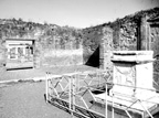 Fig. 1 - The Sanctuary of the Genius of Augustus at Pompeii - a view of the inner courtyard and vestibule. The altar is in the foreground, partially obscuring the portion of the wall surveyed and shown in Figs. 2 and 3.
That wall consists of six bays, each with a pilaster separating it from its neighbor, and each with a protrusion of about half the depth of the pilaster making an intermediate surface between the pilaster and the surface of the wall proper. A short spur wall separates the inner courtyard from the vestibule, and the bay closest to that spur wall is illustrated here (Figs. 2 and 3).
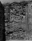 Fig. 2 - The westernmost
bay of the north wall, Sanctuary of the Genius of Augustus, inner courtyard. Note survey targets, a total
of twelve
Fig. 2 - The westernmost
bay of the north wall, Sanctuary of the Genius of Augustus, inner courtyard. Note survey targets, a total
of twelve
The photograph in Fig. 2 shows that bay and the remains of the pilasters on either side with the photogrammetry targets. There are four targets for each of the three flat surfaces to be surveyed - the pilaster surface, the wall surface, and the intermediate surface. Similar targets were placed on the wall for the next bay and for the spur wall. Since each pilaster lies between adjacent bays, each occurs in two photos, one of each bay, as do the survey targets on them.
The photogrammetric analysis consisted of entering the coordinates of the target points (surveyed on site) into the computer. Then the photographs were placed on the digitizer (an electronic drafting board), and the targets were located and related to the appropriate survey coordinates. The computer then performed a plane transformation; that is, it created a formula to calculate the coordinates in three-dimensional space represented by every point on the digitizer, starting with the premise that all such points lie on the defined plane. Once the formula had been determined, Ms. Maury traced lines directly from the photograph on the digitizer. The actual coordinates of each point picked in the tracing process corresponded to the appropriate point on the wall.
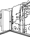 Fig. 3 - The NW corner of the inner courtyard of the Sanctuary of the Genius of Augustus. Hidden-line drawing from CAD model.
The part of the model shown in Fig. 3 is the culmination of that process. However, creating it was not so simple or direct as the foregoing might imply.
The photographic process, coupled with irregularities in the walls, introduced some distortion into the work; so the photogrammetric analysis of the common portions from two adjacent photographs did not always produce identical results. That might have been the result of lens distortion (there does seem to be some barrel distortion in the images, though it is hard to distinguish between distortion in the photographs and walls that are no longer plumb), and it might also have been the result of having only four survey points for each surface. Finally, since none of the walls is truly flat, some error may be ascribed to the problem of treating each surface as if it were flat.
We devised a way to use the two adjacent photographs to try to correct the distortion, and the results appear to be good. (Even after correcting for distortion, however, small differences between survey information from one photo and that from another remained. Therefore, we determined that material from any photograph would be surveyed only to the imaginary line marking the edge of the photogrammetric plane defined by the survey points. For instance, the photo of the north wall in Fig. 2 shows the westernmost bay. The pilaster on the right is visible also in the photo of the next bay to the east, as are the survey targets. Photogrammetry points from this photo were only taken up to an imaginary line connecting the two survey targets on the right. Material beyond that line was surveyed with the next photo.)
We also found that two surfaces meeting at nearly right angles did not necessarily generate a single line where the two surfaces met. Here, too, we devised a way to combine two good information sources to produce one better one.
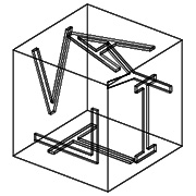
When the photogrammetric survey work has been completed, the result is a series of lines in space that mark corners, edges, perhaps individual blocks. Those lines are accurately positioned, and their locations may be queried by a user. The data points will be accurate to within a centimeter or two. But lines in space do not make a three-dimensional model; they make a so-called wire-frame drawing. (See Figs. 4 and 5 which illustrate the difference. )
 |
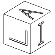 | ||||
| Fig. 4 - A child's block, drawn in a | Fig. 5 - The block in Fig. 3 as a | ||||
| wire-frame view. | hidden-line drawing. |
So the last job is to create surfaces that will make it possible to view the building more realistically - with surfaces correctly hiding objects lying behind them. The surfaces created can either be attempts to model the actual wall surfaces, or they can be designed and positioned simply to make it possible for the system to create accurate hidden-line drawings.
For this model, the surveyed lines already hold all the dimensional information; so easier-to-draw, invisible surfaces were constructed to allow the system to generate hidden-line drawings. These surfaces serve only to enhance visualization; so their positions were determined simply to be sure they would aid the viewing process. They are not part of the data one would wish to retrieve from the model. In fact, the surfaces are entirely hidden from unsophisticated users of the system
This year the photogrammetric process seems to have worked well, and the process, though not simple, is reliable. The work was more systematic, and the entire system seemed to function more easily. It is an excellent way to deal with the problems presented by the kinds of remains found in Pompeii. One problem that persists, indeed a problem built into the photogrammetry process, is that of photo interpretation. Since the photographs are black-and-white and the conditions not perfect, it can be surprisingly difficult to determine precisely what one is seeing in a photo. As a result, this is work that can only be done when people familiar with the site are at hand. Otherwise, the computer operator is obliged to become a photo-interpretation expert as well.
For other Newsletter articles concerning the applications of CAD modelling in archaeology and architectural history or Pompeii, consult the Subject index.
Next Article: The Avery Index on Disc - A Review
Table of Contents for the November, 1995 issue of the CSA Newsletter (Vol. 8, no. 3)
 Table of Contents for all CSA Newsletter issues on the Web