
|
Harrison Eiteljorg, II
(See email contacts page for the author's email address.)
When making a 3D model, no matter the software, the result can be an illustration, a true data source, or both. (It is certainly possible to accomplish neither end with a CAD model, but it is hard to imagine doing that accidentally.) Of concern here is the difference between making a CAD model in order to produce an illustration at the end of the day and making a CAD model as a data source.
 |  |
|
|
 |  |
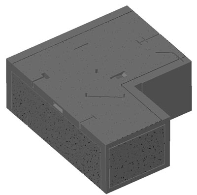
all layers showing.
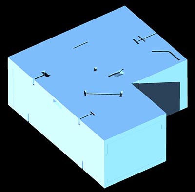
| layer showing texture boundaries.
|
 |  |
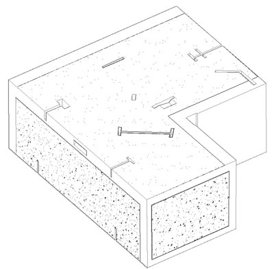
layer showing textures.
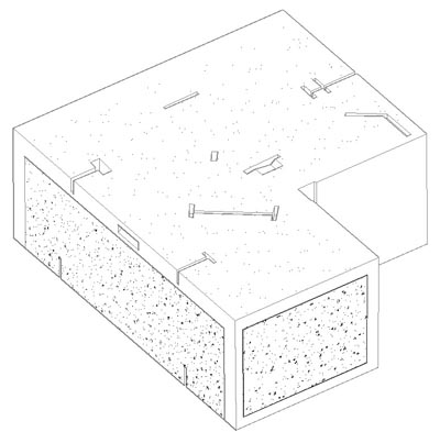
| layers showing textures and boundaries.
|
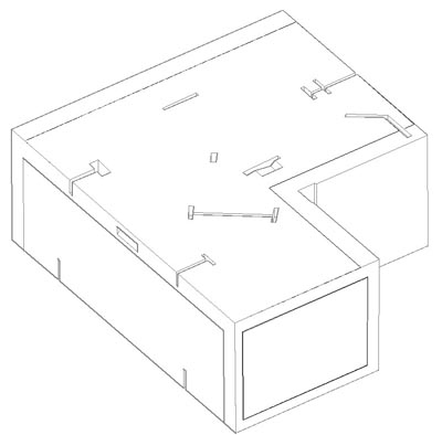
Multiple views of a single block from the north wall of the Propylaea are shown above for the sake of illustrating this discussion. All are made from the same AutoCAD model of a single block; all views are from the same vantage point. The model was made to provide the raw material for good illustrations and to provide superior data; the images above show good illustrations (not the best that could be made, given my limited skill with AutoCAD rendering procedures); opening the underlying file in AutoCAD would provide access to individual data points, calculated distances and angles, and other kinds of geometric data about the block.
This block has been modeled with the use of textures to indicate the presence of surfaces not finished smoothly and only roughly worked (either in concert with making an anathyrosis band or where precise smoothing was not deemed to be necessary by the masons). Those textures add to the utility of the illustration, making it very clear which portions of the block have been roughly finished. We used particular textures in making the model, and the choice was partly aesthetic in the sense that the chosen textures were intended to give the impression of roughly-finished marble, with one texture indicating the rougher anathyrosis surface and the other indicating a more nearly smooth surface. If the difference is not clear in the illustrations, we failed in our aims.
The boundaries of the textures were clearly indicated with lines in the model, and the textures were attached to their boundaries in the sense that changes in any boundary would automatically yield changes in the location of the related texture. As the particular textures chosen assisted in making the model more visually effective, so the use of the boundaries attached to the textures, which is not a requirement of the software, aided the use of the model as a data source. Without the boundaries it is effectively impossible to measure the location of any roughly-finished surface separately from measuring the block's faces.
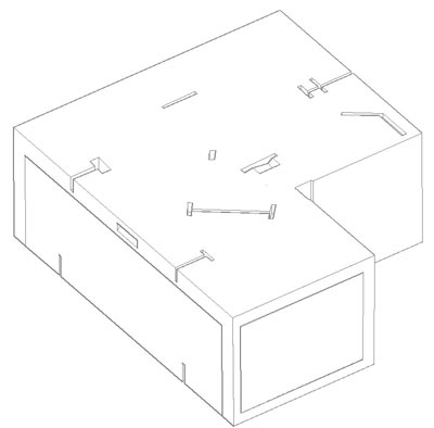
Given the foregoing information about textures and their boundaries, let us turn to some important differences among the images. (The first is a "quick and dirty" rendering that can be created in AutoCAD very simply. The second is a slightly better rendering, and the two also differ as to the presence or absence of the textures and their boundaries.) Figure 3 is essentially Figure 1 without color. Figure 4, however, is missing the boundaries of the textures. Since the boundaries are coterminal with surfaces in some cases, it is only on the top of the bock that this view can be seen to differ from the others; the boundary of the texture is obviously missing there. Figure 5 omits the textures, but brings back the boundaries. Figure 6 omits both textures and their boundaries. It is the block, if you will, stripped to its essentials and is similar to Figure 2.
The different views shown here can readily be created in AutoCAD if -- and only if -- all those parts of the whole that one might want to omit in a given view exist on different model layers. By placing, for instance, the boundary and its texture on two separate layers, each can be shown or suppressed in a given view independently. If they are on the same layer, on the other hand, both most show or both not. Similarly, each block must exist on its own layer to be shown without those adjacent to it in the model.
As a result, using AutoCAD layers as was done in making this model permitted the creation of views not only without the textures and their boundaries but with either one but not the other. Further, since the line of demarcation between textured surface and smoothed surface is not necessarily a sharp, carefully-and-intentionally-delineated line on the blocks, the more true illustrator's image is the one without the boundary but with the texture. This separation of texture and boundary, therefore, is an aid to the illustrator, making it possible to create a view that includes the texture without the boundary.
On the other hand, including the boundary is critical to the scholar who wants geometric data because it is the boundary that provides the precise coordinates of the edges of the textured areas (as measured by the draftsperson who recorded the block originally). So including the boundary is critical for the scholar but a distraction for the illustrator.
In this case, separating the boundaries from the textures aided both the data-seeking scholar and the illustrator. Furthermore, separating the blocks from one another aided both, since either a scholar or an illustrator might want to see this block alone or to see it in the company of its neighbors.
What may not be obvious is that the model-maker preparing a model for an illustrator might omit the boundary of the textured areas altogether, and the model-maker concerned only with scholarly access to geometric data might omit the textures altogether or use crude ones simply to define the roughly-finished areas. The illustrator, after all, will produce a better image without the boundaries, and the scholar has no need for textures that are meant to be illustrative.
Separating the textures from other portions of the model also makes it much easier to change the scale of the texture masks, as in the following illustration, Figure 7. This can be very important since texture scales change in their impact so dramatically with changes in the scale of the output drawing.
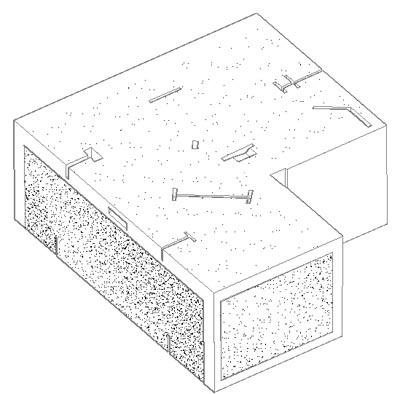
Fig. 7 - Block as in Figure 3 but with changed scale for texture.
When the models of the Propylaea blocks were made, some of the CAD technicians were more familiar with AutoCAD as an illustrative and 3D modeling tool than as a documentation tool. As a result, some used a border for the hatched areas, and some did not. (The fact that standard approaches were not specified and followed must be blamed on me, not the CAD technicians.)
In addition, the CAD models of the Propylaea blocks had somewhat different layering and layer-naming schemes. It was time-consuming but not conceptually demanding to make the layer names more similar and, in some cases, to redistribute material to new, added layers, but here again the reason for the differences was that some of the technicians did and some did not fully understand the importance of the layers and their names for scholarly use of the model.
I had not so clearly realized the difficulties here until I began the task of preparing the CAD models for archival preservation. Even detailed examinations of the models had not shown the differences clearly. Having seen them, however, it seems worth making the point here that data entry techniques can be influenced by numerous extraneous matters, not the least of which may be the specific kinds of experience of the data-entry personnel. As a result, anyone charged with oversight must be sure to be careful, clear, and explicit about the needs of the project regarding the formation of any data set. In addition, someone in that position should do a better job than I did to be certain that the job is done properly in its earliest stages so that no bad habits are built and so that, in the end, the data set does the job intended without extra work. Here we needed data but were less concerned with illustrations, and it took some time and effort that should not have been needed to put all the models into the best form to provide good geometric information -- as well as good illustrations.
-- Harrison Eiteljorg, II
(A relevant item, "Define the Audience and the Job to Build a Web Resource," by the same author, may be found in this issue of the newsletter. It concerns the need to define both audience and purpose when preparing web resources.
An index by subject for all CSA Newsletter issues may be found at csanet.org/newsletter/nlxref.html; included there are listings for articles concerning the use of electronic media in the humanities and articles concerning applications of CAD modeling in archaeology and architectural history.
Next Article: Miscellaneous Notes
Table of Contents for the April, 2009, issue of the CSA Newsletter (Vol. XXII, no. 1)
 Table of Contents for all CSA Newsletter issues on the Web
| CSA Home Page |