
|
Using a total station that requires no prism has advantages and disadvantages, some of which were pointed out in a CSA Newsletter article based on CSA experiments in the Propylaea in February of 2003 ("Surveying the Northwest Wing of the Propylaea -- A Pilot Project Project," XVI, 1 [Spring, 2003], http://www.csanet.org/newsletter/spring03/nls0301.html). One of the important results of that experiment was learning that, with the then current technology, surveying an eroded point on a block was effectively impossible with a prismless total station. (Readers unfamiliar with total stations and the issues involved here should begin with the previous article.)
As CSA personnel prepared to consider alternate ways to survey the same area, it seemed that it might have been possible to use the data from the prior experiment and to overcome the crucial problem of locating eroded block corners. This would require a process different from the one tried and found to be ineffective in 2003. In that experiment the data consisted of points surveyed on the blocks of the wall of the Propylaea and points not on the surface of the wall but deeper in the core of the wall. Fig. 1 illustrates the typical conditions that give rise to this result. The red cross is at the corner of the block, at the point to be surveyed. However, there is no stone remaining there, nothing to survey. Fig. 2 shows the result of trying to survey point D. Instead of point D, the total station obtains the coordinates of Point E.
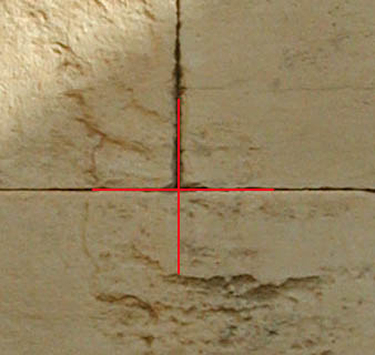
Fig. 1 - A typical joint between two adjacent blocks in the walls of the Propylaea.
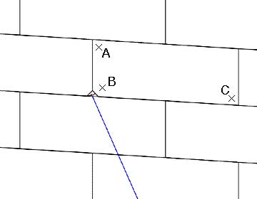
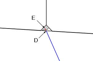
Fig. 2 - Survey points required to establish the plane of a block surface - A, B, and C (left) - Points at the corner of a block: D the point intended and E the point actually surveyed.
It is possible to locate point D, at least conceptually, because it must lie along the line of sight from the total station to point E. That is, point E lies directly behind (in terms of the line of sight from the total station) point D. Therefore, if one could locate the point where the line from the total station to point E pierces the plane defined by the surface of the block, that would be the location of point D. If the survey includes points A, B, and C, the surface upon which point D should lie will have been defined. (Three points always define a plane.) Thus, it should be possible to locate point D.
The point from which all points are surveyed, the set-up point for the total station, is one of the things established in any survey work. (Let us call that point T here.) Therefore, the line from point T to point E can be constructed in AutoCAD®. So can the plane defined by points A, B, and C. The only question, then, is whether or not one can determine the point where the line pierces the plane.
Those not familiar with AutoCAD may now wish to find something else to read. Reading on from here without some familiarity with AutoCAD is likely to prove fruitless; the key point is that the following process will locate the point where line T:E intersects the plane defined by A, B, and C -- point D. The coordinates chosen here for this AutoCAD exercise have been selected to make sure there are no horizontal or vertical surfaces that might produce accidentally accurate results. These are the coordinates to be used for the experiment (the positions of the points identified by the letters are shown in the figures above), but points B and E will be constructed in the course of the AutoCAD work, not entered directly; the coordinates are supplied as a check. Point D will be used at the outset but then eliminated in the construction process; locating it again is the aim. (Knowing the coordinates of point D in advance is necessary to prove that the correct location is, indeed, determined via this process.)
A: 100.0000, 100.0150, 5.0140
B: 100.0995, 100.0020, 4.1005
C: 102.0000, 100.0100, 4.0100
D: 100.0000, 100.0000, 4.0000
E: 97.5000, 105.0000, 3.7500
T: 110.0000, 80.0000, 5.0000
1. Enter the points as points on Layer 0.
2. Make a Layer 1 and a Layer 2. Construct the line from T to D on Layer 1.
3. Construct a user coordinate system based upon points A, C, and D. (D as the origin, C as a point on the positive portion of the x-axis, and A as a point on the positive portion of the x,y plane).
4. In that user coordinate system, construct a new point (on layer 0) at .1,.1,0 in the new user coordinate system (which will be point B). The coordinates of that point, in the world coordinate system, should be as indicated above, although translation from one coordinate system to another entails some inevitable rounding error.
5. Return to the World Coordinate System without saving the ucs created previously.
At this point, there should be a group of points on Layer 0 and a straight line on Layer 1. The points A, B, C, and D all lie on the same plane. Move point D to Layer 2 and freeze Layer 2, or erase point D.
6. Select the line from T to D and scale it by a factor of 1.25, using point T as the base. E is now the end of this line (at the coordinates given above).
At this point, on Layer 1, there is a line from T to E, and there is no remnant of the position of point D on a thawed layer. Point D must now be found. To do so, the point at which line T:E pierces the A:B:C plane must be determined.
7. Construct a new user coordinate system based on points A, B, and C. (Making this new ucs instead of using the one constructed previously means the process has not been contaminated by using the UCS established previously.) Make B the origin, C the point on the X-axis, and A the point on the X-Y plane. Save this ucs as "new."
8. Working in the new UCS, construct a line from the x,y position of T, with Z set to 0, to the x,y position of E, with z set to 0. Return to the world coordinate system.
9. Use the newly constructed line to trim line T:E. The new endpoint will lie on the A,B,C plane, and its position should be 100,100,4, the position of our original point D. There may be some apparent rounding error, depending on the number of decimal places displayed in your system.
It has been reported that there are now total stations that can directly calculate the position of point D from the information provided here, though CSA personnel have not personally seen such an instrument. Whether automatically or via AutoCAD, though, it is certainly possible to survey from some distance without a target or prism and to locate points that cannot be directly surveyed. Using this process, it would have been possible to determine the survey point locations from the February, 2003, data.
Once this routine had been determined, it seemed a natural next step to apply the process to the data gathered in February of 2003 to see how the results of surveying without a prism might compare to the survey work carried out in October of that year with a total station and carefully crafted and positioned targets. It was assumed that a way to automate or partially automate the procedure outlined here would speed the process.
The points to be compared were to be those on blocks in the second through sixth courses above the string course of the east wall of the NW wing of the Propylaea. The block corners in those courses that lie between the north wall and the area of the later window were selected for the comparison, including only those surveyed properly both in February and in October. The blocks in that area had been surveyed with both techniques and were in good condition.
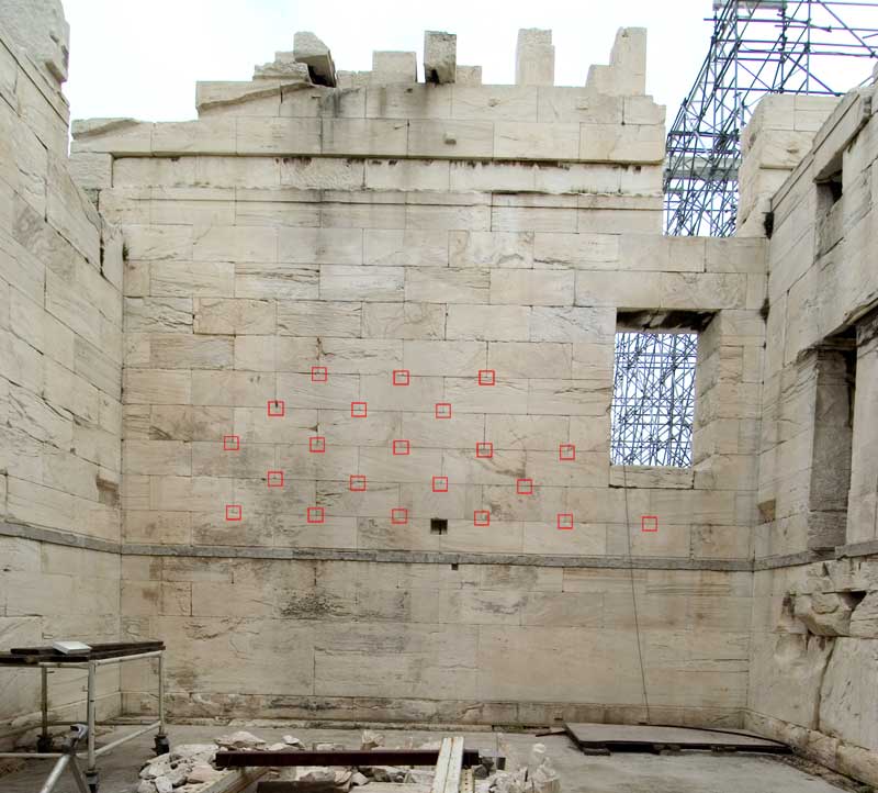
Fig. 3 - The east wall of the NW wing of the Propylaea. Red rectangles surround the surveyed corners used for this comparison.
A look at the data from the experiment with the total station without prism suggested that a simple test would suffice. In the selected area the crew working with total station but no prism had regularly identified points on adjacent blocks as lying at the same place, that is, the lower right corner of one stone being in the same location as the lower left corner of the adjacent stone. (This is the apparent situation in Figs. 1 and 2 above.) Working from the ground, at some distance from the wall and with the telescope of the total station, that was the judgment of the working crew for every pair of blocks in the subject area. The were 21 pairs of these points representing 42 block corners.
All the same block corners were surveyed in October, 2003, with total station and hand-positioned targets. In each case, the October survey data showed different locations for the two block corners. Therefore, a simple comparison of the two sets of survey data required only obtaining the distance from one block corner to the adjacent one from the October, 2003, survey. The comparable numbers for the February data were always 0 (zero). That was done for the 42 corners in the study area. No two corners had been located at the same spot in the October work, and the average distance from point to adjacent point was 2.8 mm. Of greater concern, four pairs were more than 4 mm. apart, and 9 were more than 3 mm. apart. Taking the October data as the standard to which other data must be compared, this result makes the February data unacceptable. No further testing is necessary.
Apparently the ability visually to discriminate between adjacent points through the total station telescope was not adequate for the level of precision required in this work. Finer discriminations should be made -- and they were made by project personnel when they could place targets in the appropriate positions. For other work, where discriminations of a few mm. are not critical, using a total station without a prism is indeed a good and economical approach, permitting work crews to accomplish surveying quickly and effectively from a reasonable distance. For the Propylaea with its cut-stone blocks and the consequent need for fine discriminations, however, the surveyors apparently could not overcome the problem created by looking through the telescope from a position some distance from the wall.
For other Newsletter articles concerning the Propylaea Project, or applications of CAD modeling in archaeology and architectural history, consult the Subject index.
Next Article: Parametric Modeling in AutoCAD -- Almost
Table of Contents for the Winter, 2005 issue of the CSA Newsletter (Vol. XVII, no. 3)
 Table of Contents for all CSA Newsletter issues on the Web
| Propylaea Project Home Page |
CSA Home Page |