 |
Harrison Eiteljorg, II
The CSA Propylaea Project's work to document the Propylaea is continuing, and there have been interesting results of three kinds.
First, Chrysanthos Kanellopoulos reported from Athens, via email, that, "We will include a saw blade which was inserted in the 1900's between the 5th and 6th drums and broke there -- still there!-- leaving a gap of 3 mm. between the two drums! How is that for accurate documentation?" At first glance, this kind of detail may seem irrelevant, possibly even intrusive, if you will pardon the pun. However, it is precisely the kind of detail that provides a valuable level of confidence in the accuracy of the model for those of us working on the project and for future scholars using the model. If a saw blade is properly documented, that can only show how carefully the building has been documented elsewhere.
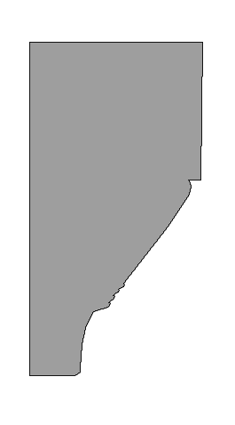
Second, a column capital from the British Museum had been drawn by Tasos Tanoulas some years ago, because it was the best preserved capital available. Although Mr. Tanoulas could draw the capital, he could only do so by making the drawing in sections. Once those sections were entered into the CAD model, they could be printed out, and now, for the first time, Mr. Tanoulas "has a plot of the profile in scale 1:1." This is the first time he has been able to see the results of his work on this capital in a single drawing. The profile is shown here in Fig. 1, albeit it at a very small scale.

Fig. 1 - Profile of a capital from the Propylaea.
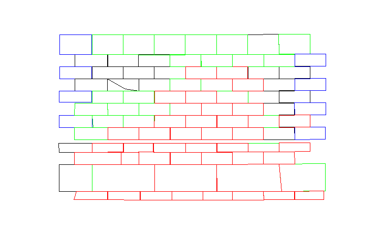
Finally, and of more general interest for those interested in CAD documentation, project personnel have been working on the north wall of the NW wing of the Propylaea, the so-called Pinakotheka. Documentation is in the form of three-dimensional coordinates of block corners, when the corners still exist, as well as other points when necessary or desirable. Since the blocks are not always proper rectangles in shape, however, there are occasional oddities in the resulting CAD model. A look, for example, at the portion of the wall illustrated in Fig. 2, shows the kind of problem encountered in this wall - blocks that appear to conflict with one another, two blocks existing simultaneously in the same physical space. Of course, multiple blocks cannot exist in the same space, but they appear to in the model if the view is enlarged greatly. That is the case, because the model follows the documentation, which indicates the position of each corner of a block but cannot be so exacting as to include the precise shape of each edge of each block. The CAD model naturally reflects that documentation, as it should.

Fig. 2 - The northern wall of the Pinakotheka as modeled from supplied coordinates
and reconstructed coordinates.
In some cases, the blocks in the CAD model that overlap do so where assumptions about missing coordinates have been supplied (see "A Spreadsheet as a CAD Aid - Again" in this issue of the Newsletter). However, there are also places where fully-surveyed coordinates have resulted in apparent overlap. A normal view of the wall will not show the overlap, but, when one looks very closely or examines the actual coordinates, it is clear that the blocks, as modeled by connecting the corners, must overlap by as much as a few millimeters. Fig. 3 is a photograph of a portion of the wall illustrated in Fig. 2 and of the adjacent east wall of the Pinakotheka; the photograph gives a better sense of the shapes of the individual blocks, and one may see from the photograph that the blocks are not perfectly regular in shape.

Fig. 3 - The north wall of the NW wing of the Pinakotheka and some of the adjacent east wall
(on the right). A larger photograph may show more clearly how the blocks are
actually shaped.

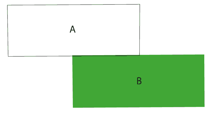
Fig. 4 shows an enlarged drawing of two of the wall blocks. A is only outlined;
B has been colored so as to show how the edges of the blocks actually intrude
into the areas of their neighbors. At normal viewing distance, this is not
apparent, but at this level of magnification it is.
The problems with apparently overlapping blocks in this wall bring up again the issue referred to in the article "Making Aims Match Needs" in the last issue of the CSA Newsletter; (v. XIV, No. 1; Spring, 2001). The CSA Propylaea Project is an attempt to create a digital model of the Propylaea from the documentation that has been generated by the scholars in charge of the building. That documentation is excellent, but it is also practical in the sense that there is a limit to the detail recorded, as there is with any structure. It is not possible to survey and record every detail; nor is it desirable. Dealing with problems such as those encountered with this wall is a necessary part of the process of converting the paper documentation into a computer model.
-- Harrison Eiteljorg, II
To send comments or questions to the author, please see our email contacts page.
For other Newsletter articles concerning the The Propylaea Project, applications of CAD modeling in archaeology and architectural history, or the use of electronic media in the humanities, consult the Subject index.
Next Article: Computing in the Archaeological Curriculum
Table of Contents for the Fall, 2001 issue of the CSA Newsletter (Vol. XIV, No. 2)
 Table of Contents for all CSA Newsletter issues on the Web
| Propylaea Project Home Page |
CSA Home Page |