
 |
Harrison Eiteljorg, II
Modeling surfaces in a CAD program can be very time consuming, but to the casual observer it is not obvious why that should be the case. An artist drawing a simple box can quickly and easily produce a drawing such as the one in Fig. 1 here. One would expect that a CAD program would make the process easier.
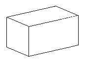
The contrary is the case. It is harder to draw the block correctly with a CAD program, because the artist can imagine the scene and draw lines only. The artist must know which lines to draw and which to suppress so that the result is "correct," but the work is a matter of drawing lines, just lines.
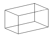
A CAD model is quite different. If the lines marking the edges of the box are drawn properly in three-dimensional space, the resulting view of the box is the drawing shown in Fig. 2 (commonly called a wire-frame drawing). The CAD program cannot generate a drawing with some of the lines hidden unless there are explicit surfaces that hide those lines or parts of lines. As a result, any surface in a CAD system must be explicitly defined as such.
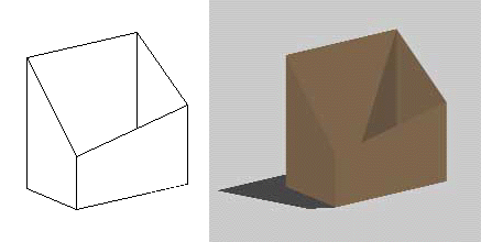
Another box is shown without a top in Fig. 3; the top is not a simple plane because of the shape of the box. Fig. 4 shows the top with a crease along one diagonal; Fig. 5 shows a crease along the other diagonal. The top of the box is the portion at issue here; it should be treated as flat even though it is not. (The shape has been exaggerated to make the drawings clear; this particular surface might not be treated as a single surface in a good model.)
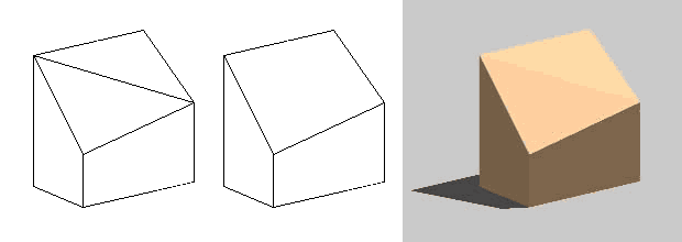
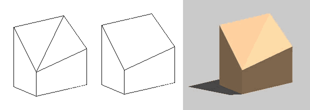
Given the four corners of the top and no other information, there is no way to determine whether Fig. 4 or 5 is the better representation of the box, and the difference will not even be apparent to most users of the model, since the crease will normally be hidden, as in the middle images of each version. Finally, the top can be drawn as a four-sided surface, as shown in Fig. 6, even though it is not flat. In this version, the shape of the top is unclear to a viewer, even when rendered, and a sophisticated user cannot retrieve further information. It is not flat, but it appears to be. Its real shape is not fully specified. That is preferable if the actual shape is not certain, as is often the case with subtly irregular surfaces. In addition, given only the four corners, there are many other possible shapes that differ in small ways from all of the possibilities shown.
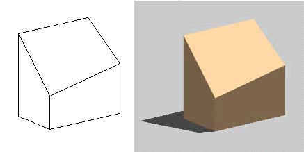
The four-sided version of the top is certainly the best choice for modeling a surface that if very nearly flat unless the survey data provide more information than the coordinates of the corners. However, if the object has more than four sides, that process will not work (in AutoCAD - even four sides presents problems in many other CAD programs). As a result, the process of modeling many-sided, nearly flat surfaces with AutoCAD involves stitching together many triangular surfaces, since the triangular surfaces are always planes, as was done in Fig. 4 and Fig. 5.
The problem is very clear when modeling a surface with a hole, for instance, a block with a cutting in it. Fig. 7 shows the same box shape used in the previous figures, but with a hole. Of course, since the box top is not flat; the corners of the hole do not form a single plane either. Now the box top must be made of 4 quadrilateral surfaces or 8 triangles, as shown in Figures 7 and 8. In each case the individual surfaces have been stitched together to give the appearance of a single surface.
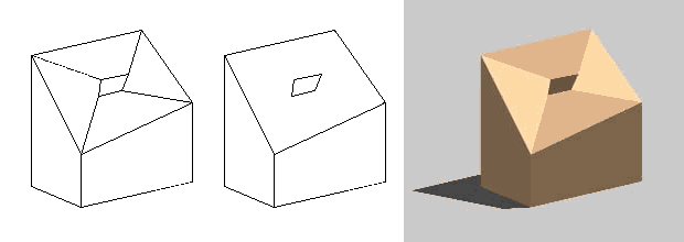
Fig. 7 - The box in Fig. 3, with a hole in the top. This version was
made with four quadrilateral surfaces making the top. Shown are a hidden-line
view with the lines between surfaces showing (left), a hidden-line view without
the lines between surfaces (middle), and a rendered view (right).
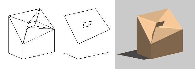
The CAD models shown in the figures all require explicitly defined surfaces, not simply lines in space. Furthermore, they require surfaces that are stitched together to appear to be one, not many, since the aim is to show the top of the box as a simple surface that seems to be flat. With explicitly defined surfaces the boxes can be properly viewed from any angle, and the appearance will be "correct" in the sense that the proper lines will show, and with properly stitched-together small surfaces the appearance of the finished model will match its real-world appearance.
Surfaces add complexity to the model-making process, but they are necessary to the effective use of a model. Complex surfaces add a great deal more complexity, but they are equally important. Understanding how to use them properly is crucial to constructing a good model.
-- Harrison Eiteljorg, II
To send comments or questions to the author, please see our email contacts page.
For other Newsletter articles concerning CAD, consult the Subject index.
Next Article: Linux on the Desktop?
Table of Contents for the Fall, 2001 issue of the CSA Newsletter (Vol. XIV, No. 2)
 Table of Contents for all CSA Newsletter issues on the Web
| CSA Home Page |