 |
A CAD model of any surface conveys the basic geometric information about that surface. That is, in fact, one of the scholarly virtues of CAD as a technology. Three-dimensional geometric information is recorded -- and retrievable -- without loss of precision due to scaling.
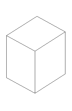
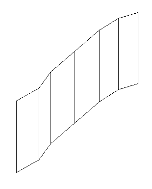
A model of a specific surface, though, conveys more information than casual users of CAD programs realize. Since any surface has a front and a back, a CAD program must know which is which; consequently, the model must somehow include information to specify the front of a surface. For instance, the block shown here in Fig. 1 is a simple, six-sided one, and all surfaces naturally face out, but which is the face of the surfaces shown in Fig. 2?
 Fig. 1 -- A simple box |
 Fig. 2 -- A series of panels |
The distinction between the front and back of a surface may seem unnecessary, but computer programs that create renderings require millions of calculations to do so, and it adds unnecessary numbers of those calculations (and time) if both the front and back of a given surface must be taken into consideration for the calculations. Therefore, the issue is not trivial.
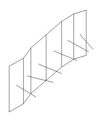
Since a CAD program must be able to differentiate between the front and back of a surface, there must be some way to identify the fronts of the surfaces. (In CAD and math parlance, the concern here is the surface normal -- a line perpendicular to the front surface and terminating at that surface, that is, existing only on the side of the surface that is its front.) Fig. 3 shows the surfaces of Fig 2 with their surface normals.

Fig. 3 -- Series of surfaces shown
in Fig. 2 with surface normals showing.
There is a simple way to control surface normals in AutoCAD, but many people make models without even thinking about the issue. The result can be a model that is difficult to use in rendering programs. I was reminded of this problem when experimenting with 3D Studio VIZ. (In fact, the delay of my review of VIZ should be attributed to the time lost re-arranging surface normals in the older propylon model. Although I thought I had properly oriented most of the surfaces in the older propylon model, many surfaces were not properly oriented.)
All surfaces are oriented very simply in AutoCAD by the order of data entry when creating simple surfaces with the 3dface command (the command used to make virtually all the surfaces of the older propylon model). Facing the front of a surface, the coordinates defining each apex of that surface must be entered in a counter-clockwise direction. That data entry sequence will create a surface facing the operator. Entering the points clockwise will, obviously, result in the operator facing the back of the surface.
This is an aspect of CAD modeling that may seem terribly arcane, but it is important for anyone wanting to create a CAD model that may be used for renderings or in a virtual reality setting. Mis-aligned surface normals will create problems in either of those uses.
For other Newsletter articles concerning CAD, consult the Subject index.
Table of Contents for the Winter, 2001 issue of the CSA Newsletter (Vol. XIII, no. 3)
 Table of Contents for all CSA Newsletter issues on the Web