 |
Parametric modeling in CAD programs refers to the use of numeric parameters (coordinates and orientation) of an object to define that object; attaching the parameters to predefined CAD entities determines the ways the parameters are used. For instance, in a parametric system a simple box might be defined as a regular box (which implies modeling procedures) with only two sets of coordinates, one for each of two diagonally opposite corners. The definition would also require three angular specifications, one to indicate the angle of the base side in the x-y plane, one the base angle in the x-z plane, and one the base angle in the y-z plane; the absence of those specifications, however, may be taken to imply zero for all. Those two sets of coordinates (x-, y-, and z-values for the diagonally opposite corners) and angular settings would be sufficient to define the box -- along with the specification that the entity is a regular box. The great virtue of parametric modeling is the ease of editing. Since the system stores the box as a standard process with a set of defining parameters, it is simple to change any parameter at any time and to obtain a new version of the block without serious effort. Simply changing a parameter changes the box.
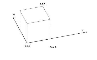
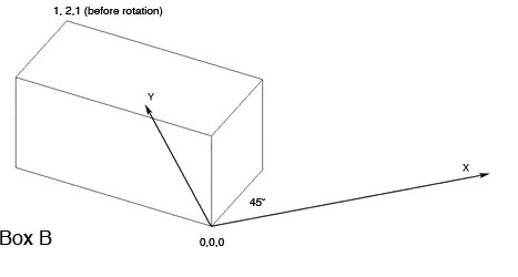
An example may be helpful. Suppose we had modeled such a box, with the base at 0,0,0 and the diagonally opposite corner at 1,1,1 (a simple cube 1 unit on a side), with angles in all planes set at zero so that the box sits on our horizontal plane, oriented to the standard compass points. Were the box generated in a parametric system, a view of its parameters would permit any of them to be edited so that the box could be changed instantly. Hence, box A below could be changed into box B simply by changing two parameters, the diagonally opposite corner from the start corner -- 1,2,1 in version B -- and the angle in the x-y plane -- 45 degrees in version B. (Note that this box has been constructed as a box with corners at 0,0,0 and 1,2,1; it was then rotated to its new position. A different set of modeling procedures, using 0,0,0 and 1,2,1 as the final corners of the box, after rotation, would have created a different result.)


Fig. 1 - Two versions of a box: A with a starting point at 0,0,0;
the diagonally opposite point at 1,1,1; and all angles within
the standard planes set at zero degrees -- B with a starting
point at 0,0,0; the diagonally opposite point at 1,2,1; and the box
then rotated so that the angle in the x-y plane is 45 degrees.
Although very few CAD programs provide parametric modeling, the ease with which individual entities can be changed makes access to a parametric modeling approach seem desirable. This is particularly striking when comparing parametric editing to attempting to edit AutoCAD's solid entities. AutoCAD solids are virtually impossible to edit, unlike simpler entities that can often be edited very easily. (The properties pane in AutoCAD shows, for example, only the following about box A: color, layer, linetype, linetype scale, plot style, line weight, and hyperlink. The "list" command for the same entity provides this information: 3DSOLID; Layer: "0"; Space: Model space; Handle = 2B; Bounding Box: Lower Bound X = 0.0000, Y = 0.0000, Z = 0.0000; Upper Bound X = 1.0000, Y = 1.0000, Z = 1.0000. None of the interior geometry can be changed. Position, color, and layer can be.)
Unfortunately, parametric modeling in the CAD world is a chimera. It is something to be sought, to be desired, but rarely to be found -- at least not with the kind of flexibility that scholarly users of CAD need. The crucial disadvantage of parametric modeling is the difficulty of using the procedure with irregular objects. It is not truly impossible to apply parametric modeling practices to irregular objects, but the parameters ultimately get buried in intricate sets of processes because complex objects must be created from multiple shapes, some of which are added to one another and some of which are subtracted from others. Many steps may be required, and the resulting set of actions and parameters becomes more and more difficult to fathom, much less modify, because each step is dependent on every prior step. As a result, parametric modeling has not been widely used in CAD programs that can model irregular objects. (Of course, parametric modeling may also complicate the ways programs must function.)
It is possible to come rather close to parametric modeling with AutoCAD, thanks to the way AutoCAD can use text. Although the program is very modern and uses a graphical interface, with mouse movements and clicks to do virtually everything, the original command-line interface still works as well. Users can simply type instructions at the command line. Furthermore, text can be pasted into the command line just as if one were typing there. (Text can also be called up to the command line from a file, a simple text file with the SCR extension. In this article the use of pasted text will be described, but the same text could be put into a text file with the SCR extension and called to the command line with the script command. The results would be identical.) Since it is so easy to create, test, modify, and re-use text in the AutoCAD command line, using pasted text is an excellent pseudo-parametric modeling system for AutoCAD. The text created can be very long, and it can be endlessly modified to be used again and again until the entity is correctly modeled -- and saved for re-use, with or without alteration.
Using pasted text in this way makes it possible to come very close to parametric modeling. Indeed, using text to model in AutoCAD at the command line can work, for all practical purposes, as well as true parametric modeling.1
Box A could easily have been modeled with text -- and remodeled as Box B by changing the text and using it again. The following text would have accomplished the creation of the original box (<cr> indicates a return at the end of the line; repeating <cr> indicates an AutoCAD entry requiring two returns to complete a sub-command):
box<cr>
0,0,0<cr>
1,1,1<cr>
When that box needed to be changed, the text would have become this:
box<cr>
0,0,0<cr>
1,2,1<cr>
Rotate<cr>
last<cr> <cr>
0,0,0<cr>
45<cr>
The CAD model maker would need to erase box A before or after creating box B if the intent was to replace Box A.
The examples shown above are very simple. First one simple box was modeled; then the text was altered to make another, somewhat more complicated box. A long and complex sequence can be approached in the same way. The steps required to model any object can be typed into a text editor and then copied and pasted in the AutoCAD command line. If the result is not perfect, the text can be edited, and a new version of the object created. That iterative process can continue until the result is correct.
Using text to model in AutoCAD is a simple technique that can be used to create any entity -- and to provide a good reference to review the modeling technique. It is not parametric modeling in one important respect, though. If the model maker selects an entity, there is no link back to the text used to create it. The model maker must keep the text for revision and re-use in some form that permits it to be found it when needed. Thus, it may be that long-term editing is not greatly aided, but, when building very complicated entities, using text that can be pasted into the command line, tested, edited, re-pasted, and re-edited until the shape is correct is an excellent way to save time, avoid laborious repetition, and create accurate models.
1. Using pasted text at the command line has been discussed elsewhere in the CSA Newsletter, most recently in "From Field Data to CAD Model: Modeling the NW wing of the Propylaea," XVII, 1 (Spring, 2004), http://www.csanet.org/newsletter/spring04/nls0404.html. The use of this feature for parametric modeling, however, has not previously been noted. Return to text.
For other Newsletter articles concerning the Propylaea Project, or applications of CAD modeling in archaeology and architectural history, consult the Subject index.
Next Article: Virtual PC and AutoCAD on CSA's MAC Computer
Table of Contents for the Winter, 2005 issue of the CSA Newsletter (Vol. XVII, no. 3)
 Table of Contents for all CSA Newsletter issues on the Web
| Propylaea Project Home Page |
CSA Home Page |