
|
Harrison Eiteljorg, II
Having experimented very successfully with the photogrammetry program called PhotoModeler® here at CSA (see "Surveying with Photographs -- PhotoModeler 5," Vol. XVI, No. 1, Spring 2003, http://csanet.org/newsletter/spring03/nls0303.html), I went off to Athens to try to apply the software to the CSA Propylaea Project work -- specifically the surveying of the Pinakotheka walls. Since the earlier work with a total station had not been either as simple or as effective as I had expected, a careful and controlled experiment was undertaken for the photogrammetry. A section of the north wall of the Pinakotheka that had already been surveyed by Dr. Tasos Tanoulas, the scholar in charge of the Propylaea, was used for the test. It was to be surveyed with both photogrammetry and a total station, and the results were to be compared with the results previously obtained by Mr. Tanoulas (published in Study for the Restoration of the Propylaea, T. Tanoulas, M. Ioannidou, and A Moraitou, Athens 1995, figs. 45-54).
The results are neither so simple nor so easily expressed as I had hoped. As a result, this discussion is both lengthy and complex. It is best broken into sections for that reason.
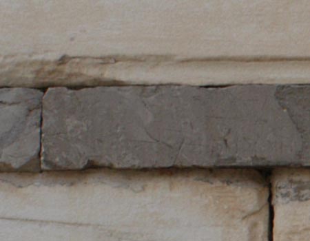
Some of this will be painfully obvious, but it was not obvious at the outset; so I think it worthwhile to make it explicit here. When people measure blocks, they stretch a tape and try to read the tape at the blocks' edges. (There is much more to careful measurement than this, but the point is that the reading is of the blocks' edges.) That is a different process from surveying a point on the block. Even if the block were perfectly preserved -- machined of metal perhaps -- putting something on its corner to serve as a target is a physically difficult task that is probably impossible in a theoretical sense. The intent is to measure the edge, the last molecule. Therefore, a prism/target such as the typical mini-prism used with total stations cannot actually be placed on the edge of the block in order to provide the kind of measurement we would take with a tape. Instead, targets on transparent material -- targets that can be aligned with the edge as a tape would be aligned for reading -- are better things to use.1 In other words, we need to be aiming at targets and positioning those targets in a very self-conscious way, aligned with the edges of blocks rather than ON block edges or corners. Figure 1 shows how difficult it is to find a point, as opposed to an edge, for measuring.
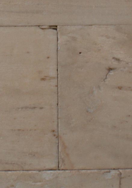 | Fig. 1 - A detail of one vertical joint in the north wall of the Pinakotheka, the NW wing of the Propylaea. |
In addition, trying to measure a corner makes the problem more severe. These blocks have endured much, and their corners are not always well-preserved. As a result, the face of the block may be missing at the corner, as may either edge. Therefore, I have come to think that measuring corners of blocks such as these may often require taking three separate measurements of each corner, one for each axis. (One measurement is taken on the vertical edge as close to the corner as possible; a second on the horizontal edge as close to the corner as possible; the third is taken on the surface of the stone as close to the corner as possible.) By doing that, we remove the need to find corners that are rarely present. Instead, we would place targets only at edges (or reconstructed edges) and on the face of the block. (A look at the published drawings of Mr. Tanoulas will show that his procedure with tapes and pre-planned planes of reference also involved three separate measurements.) This process is actually a good deal more complex than I have made it sound, and the next issue of the Newsletter will contain a follow-up article going into more detail about the process.
The point of the foregoing is that measuring with new instruments requires a more self-conscious approach to the process, and I am now persuaded that a slower, seemingly inefficient process is required.
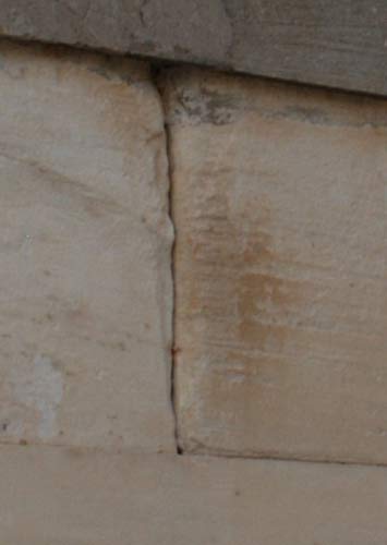
We faced an obvious problem in using photogrammetry on this wall. It is not possible to find the crucial points -- the points that matter for the survey -- in multiple photographs of the same wall, as required for photogrammetry.2 That is, it is not possible to find a point on more than one photo to represent the corner of a stone -- generally not even points for edges. While it might be possible to reconstruct a point on a given photo with various techniques, each photo would produce a different point because the angles of view keep changing, and the eroded condition of the stones makes each angle produce a different idea of the location of the true corners. (See figures 2 and 3 for two views of the same joint between stones.)
 |
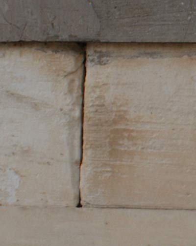 |
| Fig. 2 - A vertical joint photographed from the left. | Fig. 3 - The same vertical joint as in Fig. 2, but photographed from the right. |
As a result, the process used for this experiment involved creating a rectified image (equivalent to a head-on image) from the photos taken and then aligning the computer's cursor with the stone edges on the images. The edges were traced on the rectified images after they had been exported to AutoCAD. The first two sets of results were not as good as I had hoped; so I tried taking a non-rectified photo to AutoCAD directly (using an actual photo pasted up on a digitizer and allowing AutoCAD to correct for perspective distortion on the basis of the four points in the corners that had been surveyed -- a standard AutoCAD technique called plane transformation). That process was repeated, but the photo was marked up before printing to make the crucial points more recognizable in that second experiment with plane transformation.
These results from photogrammetry and AutoCAD's plane transformation process involved only two dimensions, those related to block length and height, not the third dimension of depth into or out from the wall surface. The third dimension was to be provided by locating specific points on block surfaces (as close to the corners as possible) and obtaining coordinates for them. It was possible to find points that could be located on multiple photos for that purpose.
Although I have relatively little experience with photogrammetry, I believe that the marking and identifying of spots on photos was done very well. As a result, I have considerable confidence in the quality of the results.
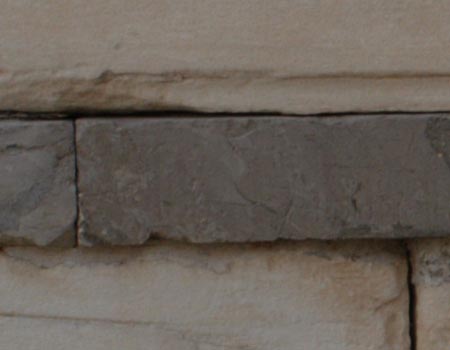
The early photogrammetry work involved one rectified image, but a second would have been required because the so-called string course protrudes from the wall and hides a small portion of the wall -- either the part just above or just below the string course, depending on the viewpoint of the camera. (See figures 4 and 5.) I created a second rectified image to show the portion of the wall hidden in the first one, and my hopes for the photogrammetry program vanished. I then had two photos of a portion of the surveyed area. One was from below the string course and one from above the string course and a bit farther to the left. When I put the two rectified images into AutoCAD together, they did not match. The discrepancies between points at block corners were more than a centimeter in areas that could be well studied. Since the aim in this work is mm. precision, that was clearly not acceptable.
 |
 |
| Fig. 4 - A photography taken from slightly above the string course. | Fig. 5 - A photography taken from slightly below the string course. |
I still think 3D photogrammetry would be useful for survey work, but not for these blocks in this place. These blocks required rectified images to be more reliably accurate than the two that were produced in this experiment.
I believe that the total station work was fatally damaged by our attempt to measure to targets placed on the blocks rather than targets aligned to the edges to the stones. The total station is not the problem. Placing the targets correctly is the problem.
The work with the total station and the photogrammetry program did not always yield survey data for the same points, and the points surveyed by Mr. Tanoulas previously were also somewhat different. Therefore, the results were hard to compare. It did not seem either effective or good practice to compare point positions; absolute positions might be slightly different while relative positions were not. Therefore, I compared instead the distances from all points to all other points in each of the survey systems. In this way the relative positions of all corners could be compared, and a large sample could be used for that comparison. There were some very interesting results, and I will summarize them in the following.
This is a complicated table, but I am trying to present all the results in one table. These figures represent only the height and width coordinates, as mentioned above, as if all points lay in a common plane. The coordinates for the depth into the wall plane were not calculated for this exercise. Numbers would have been at least slightly worse, had those coordinates been added.
All numbers here (except the number of distance measurements) are in meters
| Comparison | No. of Point- to-Point Distances |
Average Discrepancy |
Standard Deviation |
Maximum Discrepancy |
| Tanoulas/total station | 551 | .0039 | .0047 | .0290 |
| Tanoulas/photogrammetry 13 | 551 | .0049 | .0055 | .0361 |
| Tanoulas/photogrammetry 2 | 136 | .0026 | .0018 | .0085 |
| Tanoulas/plane-transformation 1 | 105 | .0045 | .0027 | .0110 |
| Tanoulas/plane-transformation 2 | 136 | .0045 | .0029 | .0118 |
| Total station/photogrammetry 1 | 731 | .0043 | .0037 | .0225 |
| Total station/photogrammetry 2 | 231 | .0037 | .0027 | .0161 |
| Total station/plane-transformation 1 | 136 | .0042 | .0031 | .0131 |
| Total station/plane-transformation 2 | 153 | .0050 | .0035 | .0175 |
| Photogrammetry 1/2 | 231 | .0020 | .0017 | .0080 |
| Photogrammetry 1/plane-transformation 1 | 136 | .0050 | .0035 | .0132 |
| Photogrammetry 1/plane-transformation 2 | 153 | .0050 | .0033 | .0136 |
| Plane-transformation 1/2 | 136 | .0032 | .0029 | .0105 |
It is noteworthy that the two photogrammetry experiments compared with one another better than any other pair. That certainly suggests that the photogrammetry work was done consistently, and perhaps properly. The second photogrammetry experiment compared well with the measurements taken by Mr. Tanoulas, but the number of dimensions was not large, and the maximum deviation of nearly a centimeter is too large.
In sum, neither the photogrammetry work, the AutoCAD-based plane transformation, nor the total station provided results that correspond with those from the survey conducted by Mr. Tanoulas. I am convinced, however, that the total station can provide good results if the targets are changed so that we can measure not to the blocks but to the edges of the blocks. Experiments carried out here support that optimism, and a coming experiment in Athens should verify it. It will, however, be necessary for me to be close enough to each survey point to place targets carefully in person. It seems that, given the level of precision required here, nothing else will suffice.
-- Harrison Eiteljorg, II
To send comments or questions to the author, please see our email contacts page.
1. We could put a mini-prism on another target so that the prism lay in the correct position, but that would be effectively the same as using a target. Return to body.
2. For this experiment a Nikon digital camera with 2,000 x 3,000 resolution was used, and the areas photographed were each about 2 m. x 3 m., making the effective resolution approximately 1 pixel per mm.Return to body.
3. The first photogrammetry experiment was done in Athens. I repeated the processes at the CSA offices with some slight variations that should not have changed the results in terms of these figures, though they might have made the point locations slightly more accurate. The two plane-transformation experiments with AutoCAD were different only in that the photo was marked in PhotoShop before printing for the second experiment. That process was intended to make the survey points used for controls more clear. Return to body.
For other Newsletter articles concerning the Propyaea Project or applications of CAD modeling in archaeology and architectural history, consult the Subject index.
Next Article: ARTstor, a Web-based Image Collection
Table of Contents for the Fall, 2003 issue of the CSA Newsletter (Vol. XVI, no. 2)
 Table of Contents for all CSA Newsletter issues on the Web
| Propylaea Project Home Page |
CSA Home Page |