
|
In February of this year CSA Director Harrison Eiteljorg, II, went to Athens to begin work on a pilot project that is a small part of the CSA Propylaea Project. The aim of the pilot project was to survey interior surfaces of walls of the NW wing of the Propylaea. Two of those walls had been surveyed by the director of work on the structure, Dr. Tasos Tanoulas, but two had not been completely surveyed. Those two walls -- the northern and eastern walls -- were the subjects of this pilot project.
The first phase of the pilot project involved the use of a new total station to survey the walls. This total station requires no prism or reflecting tape, such as those used in Pompeii, but will take measurements directly from surfaces. (If you are unfamiliar with the way a total station works, please click here to learn more about total stations, prisms, and reading without a prism.)
The great advantage to using a total station that requires no prism is simple. The survey crew does not need to hold a prism or reflecting-tape target at the place where each measurement will be made. Consequently, a prismless total station makes surveying easier and faster and does not require ladders, scaffolding, or other aids for the members of the survey team who muct hold the target in place. As it turned out, however, the use of the prismless total station was not effective for this work. One reason was apparent as we worked in Athens; another has become apparent as further testing has been done at CSA offices in Bryn Mawr.
The problem that appeared in Athens was rather simple. The intent was to survey the ashlar blocks of the walls. To do so, each of the four corners of each block was to be surveyed with the total station (along with interior details for such things as lifting bosses). The process involves aiming (through a telescope) at each corner in succession and then activating the measurement and calculation routines. The problem is that the corners are usually not there. Even the best preserved blocks have eroded edges and corners. The machine operator can still aim at the correct point, using the edges to align the crosshairs in the telescope. Having aimed correctly, the operator has two of the three pieces of information required (swing angle and elevation angle). The reported angles are not affected by the absence of the corner so long as the operator can see clearly enough to aim well. The third piece of information needed is the distance to the point. To get that item, the operator activates the distance measuring device that is built into the total station.
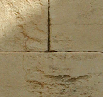 Fig. 1A |
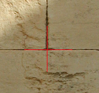 Fig. 1B |
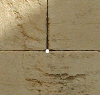 Fig. 1C |
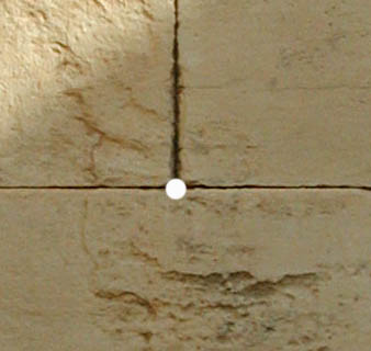 Fig. 1D |
|
Fig. 1 - Four versions of a photograph of the east wall in the Pinakotheka. As is shown in Fig. 1A, the corner where the two upper blocks meet is obvious, but both stones has been eroded at the corners. Fig 1B shows how easy it is to align crosshairs on the point that should be the corners of the blocks. Fig. 1C shows the area that might reflect the EDM beam for a distance measurement, and Fig 1D shows a larger area around the actual point being measured. The angle measurements would not be affected by the size of this area, but the accuracy of the distance measurement certainly would. | |
In the conditions extant in the Propylaea the activation of the EDM sent a beam toward the corner of the block, BUT there was no stone precisely in that spot because of the erosion. As a result, the distance measured had to be in error to some extent. The beam was reflected by the stone around the missing corner, including the faces of the adjacent stones and the surfaces that had become exposed only because of erosion.
Knowing the potential problem, the surveyors took another measurement for each corner but with the total station aimed at the surface of the stone where it was not eroded. That measurement was taken to provide a correction.
In fact, the correction may have been adequate to determine the plane of the wall face, which would have been improperly located by a measurement at the corner. However, the survey process produced other error, not just the incorrect location of the wall plane. The problem is illustrated in Fig. 2, which is derived from a CAD model created in Athens to illustrate the problem better.
 Fig. 2A |
 Fig. 2B |
|
Fig. 2 - Total station distance measurement of block corners. Fig 2A shows the situation when measuring blocks that have not been eroded. The blue line represents the beam from the EDM. Fig. 2B shows the situation in something akin to the norm for the Pinakotheka walls, and Fig 2C is a detail. The blocks have been eroded at the corners; so the beam (again a blue line but with a red extension to the point actually measured) passes by the corners. Not only is the distance wrong; all the coordinates would be in error because the calculations would find the location for the end of the red line, not the end of the blue line. (As noted above, the area covered by the beam projected from the EDM is not specified; so this drawing, which indicates a single line, is hypothetical and cannot be precisely correct.) |
 Fig. 2C |
The aim of this work is to produce millimeter-level precision, but it became apparent that the prismless total station would not produce measurements with that precision. The work was stopped.
Further testing was undertaken at CSA offices in Bryn Mawr. That testing had to do with a related issue -- what does the electronic distance measuring device actually measure? That is, when the beam is activated to take a distance measurement, the beam covers some discreet area at the aim point, not simply a point. However, it is impossible to know the size or shape of the area at or near the target that is struck by the beam although that may have an impact on accuracy and precision.
Total stations that require a prism or other reflecting target do not share the problem of an unknown reflecting area. Therefore, such total, stations, including the CSA total station, are not affected by the surface(s) at which the EDM is aimed. Surrounding stone, brick, metal, wood, or whatever will not reflect the infrared beam back to the total station. In fact, that turns out to be a significant advantage for using a total station that requires a prism/reflector. Users can be sure that the EDM will read only from the prism/reflector.
Nevertheless, the position and angle of reflective tape, when used in place of a prism, can have an impact on measurements. Thus, when Mr. Eiteljorg returned to the U.S. and began experimenting for the next phase of the pilot project, several experiments were conducted to test the necessary size of the reflecting tape, its position relative to the point to be surveyed, and its orientation relative to the total station. The results of the tests may be summarized as follows. (Using a prism, this is not an issue; the prism is normally placed directly in the line of sight and facing the total station.)
So long as the reflecting tape is oriented perpendicular to the EDM beam, the piece of reflecting tape can be very small. At about eighteen meters, the machine could read accurately from a square piece of tape only about .5 cm. on a side.
If the reflecting tape is perpendicular to the EDM beam but not actually on the target point, as in Fig. 3, the machine will still get a reading. However, the reading will be, as it should, the distance to the center of the tape, which may be very slightly different from the distance to the target.
If the tape is not perpendicular to the EDM beam but at a moderate angle (under thirty degrees), a reading may still be obtained, depending on the nature of the tape and its size. The distance measurement, though, will be to the center of the tape, and the orientation and position of the tape may change that measurement, though by small distances, and the resulting calculations.
When precise measurements are needed, considerable care is required. As the EDM beam angle deviates from perpendicular, the position of the tape becomes more critical. (No less critical is the position of a small prism.)
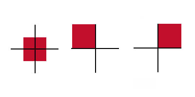 |
| Fig. 3 - Possible orientations of reflecting tape relative to the aim point. These drawings show where the reflective tape (red) might be positioned relative to the aim point (crosshairs). In each of these cases the tape would be close enough to the aim point to provide a reading. However, only the position shown at the left, with the tape symmetrically positioned relative to the aim point, would provide a reliably accurate reading. Each of the other two positions show the tape close enough to the aim point to provide a reading, but the reading would be in error if the center of the tape were farther from or closer to the EDM than the aim point, as would generally be the case. The magnitude of the error would depend on the angle at which the tape lies relative to the EDM beam. |
Because small prisms are generally too bulky to fit in tight places and because of the difficulties with tape orientation and position, CSA's preferred procedures in the future will be as follows:
A total station that requires a prism or reflecting tape will be used.
When conditions permit, a target with reflecting tape and crosshairs will be used. See Fig. 4 for a photograph of a CSA target.
 | Fig. 4 - This target is the one designed by CSA for use with a total station. When printed on clear acetate, the white area is transparent. As a result, the cross-hairs and central dot permit precise placement of the target on the subject, with the center exactly at the point of interest. Precise aiming with the total station telescope is also aided by the combination of cross-hairs and central dot. |
When that is not possible -- for instance, in tight corners or when a surface is too irregular -- a small piece of reflecting tape will be affixed to the head of a pin of measured length, and the point of the pin will be positioned at the point to be measured. The head will then be aligned with the EDM beam so that its center is measured, keeping the point always on the point to be surveyed. (The length of the pin will be treated as an offset in the calculations performed by the total station or its data recorder.) Fig. 5 shows such a targeting pin, in this case a golf tee with tape on its head. The golf tee is useful for making targets; it can be cut to length, and a specific length may be required by the total station software.
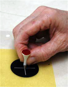 Fig. 5 - CSA targeting pin. |
These guidelines are meant to be practical; so adjustments will certainly be made as they are put into practice. CSA experience with them will be reported in the Newsletter.
A total station is an electronic transit for reading swing angles (deviation from north) and elevation angles (deviation from the horizontal) when sighting from a known point to an unknown one. In addition, a total station includes an electronic distance measuring device (EDM) that emits an infrared or laser beam that is reflected back to the EDM. Using timing algorithms, the EDM can determine the distance from itself to the reflecting surface. Early EDMs required a prism/reflector to reflect the beam back to the EDM; recent iterations of the device can operate with the reflections from real-world objects, although the objects in questions must reflect at least a portion of the light striking them. Using a total station that required a prism/reflector at Pompeii, CSA personnel were able to get good readings from bicycle reflecting tape at short range (under 50 m.) rather than a surveying prism.
The information provided by a total station -- swing angle, elevation angle, and distance -- are all that is necessary to calculate the location of the target with trigonometric formulae, presuming that the location and orientation of the total station itself are known.
The last part of the total station is sometimes built into the unit and sometimes separate. It is the data collector that records measurements so that they can be downloaded to a computer. Those measurements may be either the "raw measurements" (the angles and distances) or the calculated data points derived therefrom. Without a data recorder, the operator must manually record information for each survey point during the work process.
For greater detail, H. Eiteljorg, II, "Using a Total Station," CSA Newsletter VII.2 (August 1994), http://csanet.org/newsletter/aug94/nl089407.html. and H. Eiteljorg, II, "New Total Station - Surveying in Pompeii," CSA Newsletter VIII.2 (August 1995), http://csanet.org/newsletter/aug95/nl089506.html.
For other Newsletter articles concerning the applications of CAD modeling in archaeology and architectural history or the Propylaea Project, consult the Subject index.
Next Article: Europe's Digital Inheritance: ARENA Archives Launched
Table of Contents for the Spring, 2003 issue of the CSA Newsletter (Vol. XVI, no. 1)
 Table of Contents for all CSA Newsletter issues on the Web
| Propylaea Project Home Page |
CSA Home Page |