
|
|
|
Using AutoCAD to Construct a 4D Block-by-Block Model of the Erechtheion on the Akropolis at Athens, II: Connecting a Database to an AutoCAD Model
Paul M. Blomerus and Alexandra L. LeskIn the first article in this series (Using AutoCAD to Construct a 4D Block-by-Block Model of the Erechtheion on the Akropolis at Athens, I: Modeling the Erechtheion in Four Dimensions," CSA Newsletter, XX, 2; Fall, 2007) we presented a method by which one can add a fourth dimension, namely time, to computer visualisations of ancient sites. To enable this, we created a database linked to a CAD model that allowed the objects in the model to be manipulated from outside the CAD model -- a principle that has wide application in ancient architecture and archaeology. This article sets out the method used to connect a spreadsheet (equivalent to a flat-file database) or a database to our AutoCAD model of the Erechtheion using AutoCAD-readable layer state files.
The advantages of using a database to manage and manipulate the properties of objects within a CAD model were discussed in the previous article in the series. As argued there, with this system the CAD model can focus on the information that it portrays best, namely the geometric and spatial information. Dates of construction or functional usage are almost always interpretations of evidence and fit better in a database where any inconsistencies can be explained and the primary sources cited. Such a database can even cope with multiple alternative interpretations. It leaves the CAD modeler free to concentrate on spatial and geometric matters while the database contains interpretive information. Once the details have been established, they can be added, changed and updated without even opening the CAD model.
This approach has particular application on archaeological excavations and in architectural restoration projects. On archaeological field projects, it is a common problem that excavated walls cannot be dated right away. However, they must be drawn and recorded soon after discovery. The actual date may not emerge till much later, with final decisions not being reached for several seasons or even decades! Archaeological projects typically employ some sort of color-coding or layer naming convention to suggest the date for walls or other architectural features in a CAD model. The architect or draftsperson is usually therefore faced with a quandary. What color should be assigned to the newly excavated wall? A brief consultation with busy field archaeologists usually ensues, and an assumption is made. What if there is a debate amongst the team of archaeologists? Further evidence may accumulate for the date, but what ensures that the object color is updated? Discrepancies sometimes only come to light when drawings are needed for publication but, then again, inconsistencies often remain undetected for many years.
The method proposed here alleviates all of these issues: the architect or draftsperson has only to record the spatial information about objects on the site. A database is set up for the interpretive and dating evidence. So long as the database contains the necessary information, a decision can be made about the appropriate color or line type in the drawing for all objects according to the requirements of the data and the individual drawing. Several representations can be easily produced if alternative interpretations of the evidence need to be illustrated. Besides which, setting up a database of excavated architectural objects is an excellent idea and something that archaeological field projects often devote less effort to than they should, especially when compared to the elaborate small finds or pottery databases. The rigor and discipline of uniquely labeling and recording evidence about each architectural object required by this method will be an investment well worth the trouble even without the linkage to the CAD model.
Where ancient architecture is concerned, the project often calls for the creation of depictions of the building showing it in a specific state of construction, decay or restoration. There is also often a need to show only a subset of walls or blocks in order to illustrate a theory or to show a particular detail. For instance, in creating a cutaway view, a wall may need to be temporarily "turned off" to allow a view of the interior of a complex of rooms. The method presented here allows non-CAD-trained project staff to select quickly which blocks or walls should be turned on or off in the CAD drawing for a particular, desired depiction.
The basic requirement to use this strategy is that each object (or group of objects), be it a wall or a block in a building, has a unique identifier in the CAD model. This is accomplished by letting each CAD layer contain only one object or group of objects with identical characteristics. In the case of a building, this unique identifier can come from a grid scheme such as the one used on our Erechtheion project; in the case of an archaeological site, this would usually be a number assigned during excavation that included some site grid reference information and an alpha-numeric code.
Basic Outline of the Method
The method of linking the database to the CAD model we created relies on the use of AutoCAD layer state files (files with the three-letter extension LAS). The layer state file is a simple text file used by AutoCAD to store the characteristics of layers (on/off, frozen/thawed, linetype, color, etc.). Current saved layer states can be exported to layer state files by the AutoCAD Layer States Manager for later import to recreate the current states of all layers. For the method used here, a layer state file is created not by AutoCAD but by an external database or spreadsheet program. Importing that file creates layer states desired by the draughtsman. By creating and manipulating the contents of the data file, a layer state file is created wherein the properties of layers in the AutoCAD model (and hence objects within each layer) are set to reflect the desires of the draughtsman at any moment. The process is described in outline here, and another article in the spring CSA Newsletter will set forth in more detail the processes required.
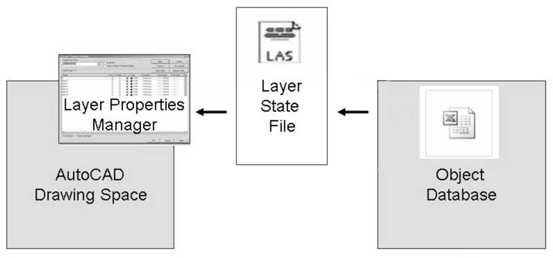
Fig. 1 - Data Structure
The basic data structure is shown in Figure 1. Information about each object in the AutoCAD model is stored in the Object Database including the desired status in the drawing (on/off, color, line type, etc.). These data are exported into an AutoCAD-readable Layer State File. This file, in turn, is imported into AutoCAD so that the properties of the objects in the drawing become those in the layer state file and hence reflect the status in the Object Database. Such a simple Object Database can be set up in Microsoft Excel, but you could equally well use FileMaker or any other database programme.
To start with, you will need to assign each of the objects (or groups of objects) in your drawing a unique layer name which is set equal to the unique identifier you are using on your project to designate this object (or group of objects). While we have previously mentioned using the CSA Layer Naming Convention, the layer names can be chosen according to any unique pattern. On the other hand, retaining some aspects of the CSA Layer Naming Convention will permit a CAD draughtsman to take advantage of the layer names while working.
With layer names assigned, each name becomes the key element in the database -- the basic column in a spreadsheet or the primary key in a data table. (If you are using an AutoCAD master file which contains x-refs to sub-files as we did on the Erechtheion project, then each layer name will have a prefix of its individual file name). The database contains columns for all relevant characteristics (function, date, etc.), one per column in the case of a spreadsheet but perhaps a more complex format in the case of a relational database. All characteristics of the model entities that might be of interest in choosing what to display or what colors to use in a given drawing must be included.
In the next article we will provide examples of an object database and a sample AutoCAD drawing to illustrate the possibilities of this method.
Additional Thoughts
The database, which in our case was a spreadsheet, can contain as many columns as you wish with as much or as little data on each object as you need. As stated earlier, a proper design will allow the database to cater for alternative interpretations of the evidence. Alternative interpretations can then be exported as different layer states that will, for instance, assign different colors to walls or blocks within the AutoCAD drawing depending on the interpretation.
If a database already exists for your project that contains information about the objects you are drawing, it could be synchronized with your object database so that key information about the object is not repeated.
As an aside, for this method to work correctly, all the objects must have their color, linetype and lineweight properties set to "by layer" to be manipulated by the layer state file.
Note that if you create new objects in the AutoCAD model and assign a new layer name in the model, they will not automatically be added to the database. You would need to set up a process for the registration and creation of new objects in the database for all new layers in the AutoCAD model. Most archaeological projects already run such a process for the assignment of find numbers or excavation units. You can quickly run a consistency check between the database and the model by exporting an "all layers" layer state file and then comparing the list of layer names to the contents of the database.
Conclusion
We have presented here the outline of a method for linking a database to an AutoCAD model using AutoCAD's layer state files. The method permits objects in the model to be manipulated from outside the CAD model. The procedure can be automated so that non-CAD-trained experts can manipulate the appearance of the AutoCAD model without opening AutoCAD themselves. For project architects, this could mean a counter for requests such as, "I know you are busy but... can you just create me one more view with this bit taken away and this other part shaded in a slightly brighter shade of cyan . . .": "Give me a layer state file exported from the project database with what you want and I will plot it for you from any angle you like!"
This method of modeling, whereby each object in the model is assigned a unique identifier, with its properties stored in an external object database, is highly recommended for archaeological AutoCAD modeling, both for architectural surveys and site-based projects.
-- Paul M. Blomerus and Alexandra L. Lesk
For other Newsletter articles concerning CAD or the use of electronic media in the humanities, consult the Subject index.
Next Article: Web Site Review: Digital Egypt and the OEE Scenes-Detail Database
Table of Contents for the Winter, 2008 issue of the CSA Newsletter (Vol. XX, no. 3)
 Table of Contents for all CSA Newsletter issues on the Web