
|
In October Mr. Eiteljorg went again to Athens to survey the walls of the NW wing of the Propylaea. Two previous efforts had involved technologies that permitted surveying from some distance. In the first experiment a total station that worked without a prism was used, but there were problems, as reported -- CSA Newsletter, Vol. XVI, No. 1, Harrison Eiteljorg, II, "Surveying the Northwest Wing of the Propylaea -- A Pilot Project," http://www.csanet.org/newsletter/spring03/nls0301.html. The second experiment was with photogrammetry, and it also failed, as reported -- CSA Newsletter, Vol. XVI, No2, Harrison Eiteljorg, II, "More Survey Experiments on the Propylaea," http://www.csanet.org/newsletter/fall03/nlf0301.html.
On this occasion, the work was carried out in a somewhat less hi-tech fashion. A total station was still used, but Mr. Eiteljorg or David Scahill, a new member of the CSA Propylaea Project team, held a prism on the point to be surveyed for each survey shot. This system, of course, is neither particularly difficult nor new, but there are more difficulties than first meet the eye and some lessons to be learned about how to go about this task efficiently.
One complication was the need to get either Mr. Eiteljorg or Mr. Scahill up on the wall high enough to place the target appropriately - and the wall is about ten meters high. Using ladders was an obvious possibility, but the time required to position and re-position ladders was judged to be excessive. (The target could only be held in place for a very small area near the top of a ladder and within arm's reach; so it would have been necessary to re-position the ladder almost constantly.) In addition, a person on a ladder presents a significant problem for the operator of the total station. Either the person or the ladder - or both - may block the view of the target from the machine. In such cases, some movement is possible, but limits on the ladder's stability make it difficult for the person on the ladder to move out of the way.
Fortunately, it was possible to borrow from the Acropolis work crews a piece of equipment called a man lift, which can be seen in Fig. 1 just after the Propylaea crew had managed to get it over the threshold and into the NW wing of the Propylaea. This is simply a small platform on a hydraulic lift. The platform (with surrounding rails to make it safe) can be pushed straight up in the air to a height of 9 meters. However, the higher one goes, the more difficult it becomes to see the target from the total station; more and more of the platform and the man on it block the view. The problem is similar to that of a man on a ladder, but there is more room for movement without concern for the balance of the ladder. The man and the platform both blocked the total station on occasion. but it was always possible - at least in this project - to maneuver the machine or the person or both so that a direct view of the prism could be obtained.
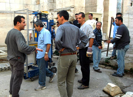
Fig. 1 - The man lift in the NW wing of the Propylaea along with the members of the Propylaea crew who lifted it over the threshold.
The man lift cannot be placed too close to a wall. Its base needs room, and it also uses outrigger extensions from the base to make certain that it cannot tip over. It was possible to bring the outriggers very close to the body of the machine on two sides but not the other two. While the outriggers made the machine more safe, they also made it difficult to get close enough to the walls in some areas.
Once up in the air, Mr. Eiteljorg and Mr. Scahill could position a target on any point that could be reached. The higher they went, though, the harder it was to reach out to the wall and position the target. Once the machine had lifted its occupant about 5 m., it began to shake a good deal, and neither man was eager to reach out to the wall in the same carefree way used lower down. Indeed, both exhibited a strange posture as the machine got higher, one that can be described as stiff-kneed, with hind-quarters pushed back, as if to balance any forward movement of the upper body. That posture is illustrated in the photo here of Mr. Scahill (Fig. 2); fortunately, I was not photographed in my version of this posture. The whole group working on this project is shown in Fig. 3.
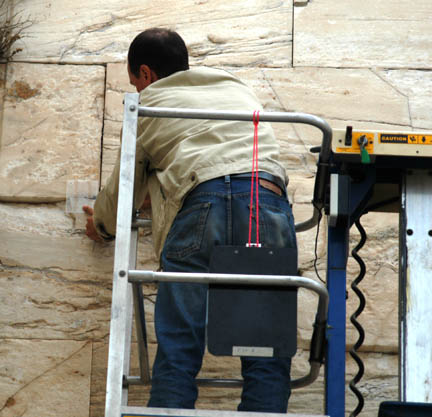
Fig. 2 - David Scahill on the man lift.
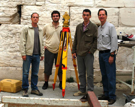
Fig. 3 - David Scahill, Vangelis Pentzas (surveyor), Chrys Kanellopoulos, and the author.
(I must admit to a little creative PhotoShop activity here. I took a photo of my three
colleagues, and Mr. Kanellopoulos took a photo of Mr. Scahill, Mr. Pentzas,
and me. My image was taken from the second photo and pasted into the first to
make this composite.)
Along the wall at its lower levels, it was relatively easy to work on a rolling cart that sits normally in the NW wing or on a ladder.
No matter whether working on the cart, a ladder, or the man lift, the job of Mr. Eiteljorg and Mr. Scahill was straight-forward, if not always easy.
A target was created for the work. It was made of transparent material with cross-hairs and a dimple at the meeting of the cross-hairs. When the cross-hairs were positioned at the proper location -- which could be checked visually since the material was transparent -- the operator of the total station could aim the instrument precisely at the cross-hairs. Once he had aimed, a prism could be put into place on the dimple at the meeting of the cross-hairs. Then the instrument could be activated so that distance was measured and angles were recorded. (The reflective tape that works on the CSA Pentax total station and eliminates the need to rely upon a prism does not work with the Topcon total station in Athens, and no alternate reflecting tape could be found.)
There were, of course, places that could not be reached with the target. For instance, we could not place the target on points close to internal corners. In such places we put the target a measured distance away (on a horizontal line and on the local surface) so that a correction factor could be applied later.
There were other places where stones were too damaged to permit locating a corner. In such instances the target could be placed along the horizontal edge as near the corner as possible; a reading there would provide the elevation of the missing corner. A similar measurement taken along the vertical edge near the corner would yield the second coordinate. A third placement of the target, on the surface as near the corner as possible, provided the third coordinate.
In still other places the stones were so damaged that we had to take measurements on surfaces where they survive, construct multiple surfaces for each stone, and then define the edges of stones with the intersections of the surfaces.
Several combinations of these techniques were used, and most of the east and south walls of the Pinakotheka were measured.
There was an unexpected problem with record keeping. When either Mr. Eiteljorg or Mr. Scahill was holding the target, Mr. Kanellopoulos took notes. Mr. Eiteljorg had planned on written notations rather than drawings, but Mr. Kanellopoulos was more comfortable with drawings. Some confusion resulted, though nothing that could not be fixed. (Mr. Eiteljorg had planned to use a digital recorder to make notes as they worked, but the absence of an external microphone made the recorder too difficult to use. It would be interesting to have the information from a recording to see what help it might have offered.)
The operator of the total station had some difficulty with the targets originally supplied by Mr. Eiteljorg. As a result, new targets were made. The design is shown here in Fig. 4. Note that there are parallel lines for the cross-hairs. Because of the frequent need to place targets a measured distance from the point to be surveyed, this new target also incorporated measurements along two edges to assist. Oddly, when the scales were checked against a standard (an important precaution) the lengthwise printing along the right edge, if continued, resulted in a deviation from the correct length of at least a mm. in 10 cm. That is why the scale on the left edge does not continue beyond 5 cm.
Fig. 4 - The design for the target used on the Propylaea survey.
The targets were printed on very thin, clear acetate. As a result, they were not as durable as might be most desirable. However, the thinness of the material made it possible to place the prism directly on the acetate without concern about error resulting from the thickness of the material.
The acetate targets could also be laminated. However, laminating material adheres primarily to itself, requiring two sheets that overlap the target that is trapped between them. Overlapping the edges makes the scales more difficult, and trimming the laminating material back to the edge of the target limits the sturdiness of the result. In the end, it seems the plain acetate may be the best solution for areas where the scale on the edge is needed and the laminated ones elsewhere. In either case, one must have a ready supply of replacements as those used wear thin or lose some markings.
The results of the survey work on the walls that had not been previously surveyed cannot be tested against any standard; so a few measurements were taken on the already-surveyed north wall to compare them to those taken previously by Mr. Tanoulas as a test. Twenty-one dimensions (based on seven individual survey points) were compared. On average, the dimensions taken by Mr. Tanoulas differed from those taken with the total station by 1.21 mm.; the standard deviation was 2.36 mm.; the largest discrepancy was 6.96 mm. While the largest discrepancy was larger than I would have liked, the average and standard deviation suggest that this method is as we had assumed - very reliable. It may not be physically easy or extremely hi-tech, but it works and works well.
For other Newsletter articles concerning the The Propylaea Project or applications of CAD modeling in archaeology and architectural history, consult the Subject index.
Next Article: From One Context to Another: Building a Common Information Environment for Archaeology
Table of Contents for the Winter, 2004 issue of the CSA Newsletter (Vol. XVI, no. 3)
 Table of Contents for all CSA Newsletter issues on the Web
| Propylaea Project Home Page |
CSA Home Page |